
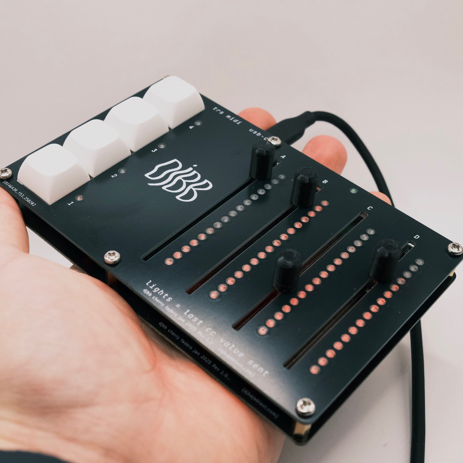
I’m of the opinion that faders are better than twist pots, and wanted something compact that I could use to control a bunch of parameters in an Ableton drum rack. I also wanted to solve the “jumping” problem that you have when using a controller with multiple banks – if you change a bank, you don’t know what the real position of the knob should be, and it’s easy to accidentally jump to a wildly different value than you want just by slightly moving the potentiometer. Here are the features that the LumaFader has, some of which help solve this problem.
Demo
Features
- 4 x long-throw faders for precise control
- 4 x mechanical keyswitches for bank management
- 16x RGB LEDs per fader to show the last fader position for that bank
- “Pickup” mode – only send a message when the last value is passed
- USB C for easy connection to your computer / phone / whatever
- Mini TRS Out to directly connect to a synth
- 17 banks = 68 total assignable sliders
Usage
I designed this to use with a drum kit in Ableton. For example, you can map the global sliders to overall kit FX (reverb, volume, filter, etc.). Then, map each bank to an individual sample’s parameters. So holding one button will access 4 parameters of the drum sample, holding another button will access 4 parameters of the snare sample, etc.
- Move slider(s) to send CC messages
- Hold button(s) to access other banks of CCs
- Double click a bank button to lock the bank (otherwise the global bank will be used if no buttons held)
- CC messages are only sent if the slider moves past the last value sent (as displayed on the LEDs next to each slider)
- You can also enable jump mode – send CC messages immediately if the slider is moved
Design
I had already successfully designed a custom PCB based off of the RP2040 – see the Loopster 2.0 – and each time I design a PCB, I try to do something I haven’t done before in order to improve. In this case the new elements were USB C – I’ve only ever used micro USB in the past – and the use of a large number of RGB LEDs (NeoPixels). I’ve used these pixels in the past, but this project uses 69 of them – a good factor of 4 more than the Loopster 2.0 has.
First, I had to add the RP2040 and the associated circuitry. Following the RP2040 hardware design guide I added the appropriate power regulator, memory chip, crystal, and decoupling caps. The only changes I made from the official design:
- Swapped the ceramic cap on the power supply with an electrolytic – something that a Redditor suggested. This seems to have eliminated the high pitched buzz you can sometimes hear.
- Swapped micro USB for USB-C. This ended up being simpler than I expected – just needed a few extra resistors
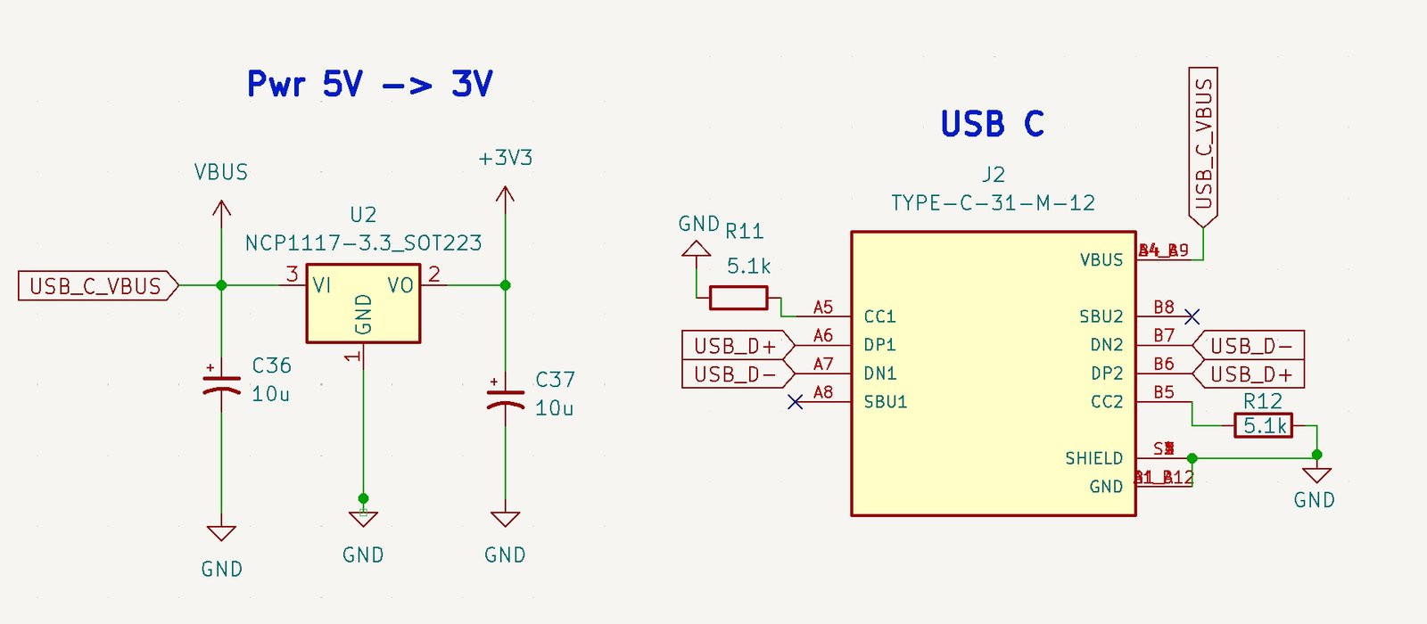
power regultor and USB C changes
The rest of the circuitry is pretty straightforward – connect the slide pots to the analog pins of the RP2040, connect each button to a digital pin, and then connect the neopixels to one digital pin. These tiny addressable RGB LEDs are great in that they only require ONE digital pin for all of them. Finally, add the TRS MIDI Out circuit, which requires just one more digital pin.
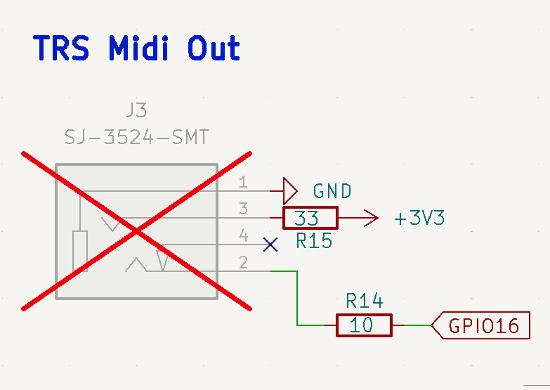
TRS Midi Out Setup
Here is the full schematic
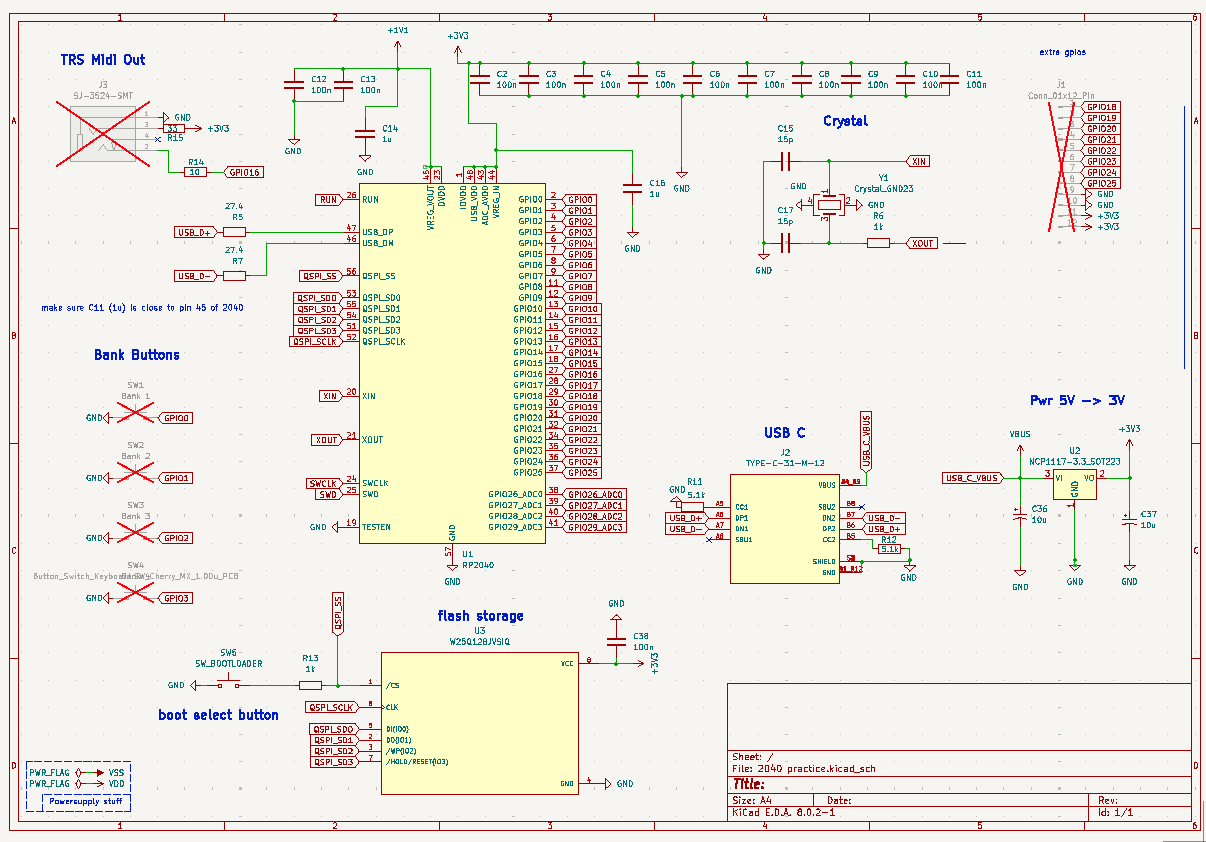
Full Schematic – Main
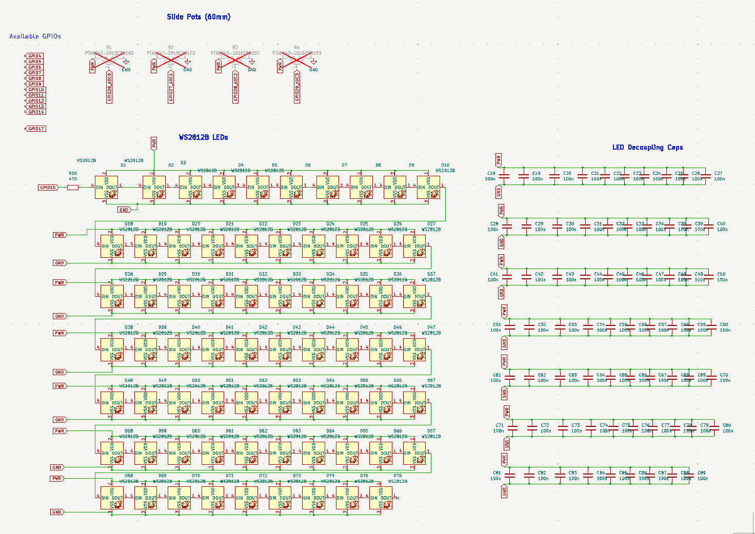
Full Schematic – LEDs and Pots
Layout
The goal was to make this device compact and portable, so efficient use of space was a priority. I used the middle of the board to house the main circuitry, the left for the buttons, and the right for the 4 large sliders. I decided to break out some additional GPIOs from the RP2040 since I didn’t use them all. I don’t have any plans for these, but perhaps in the future they can be used for something?
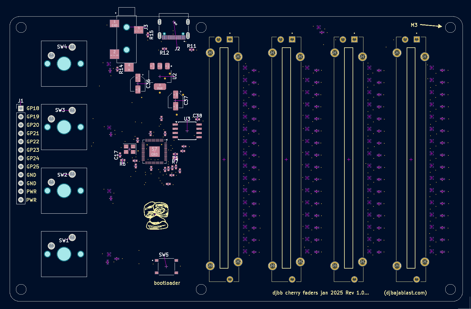
PCB Layout
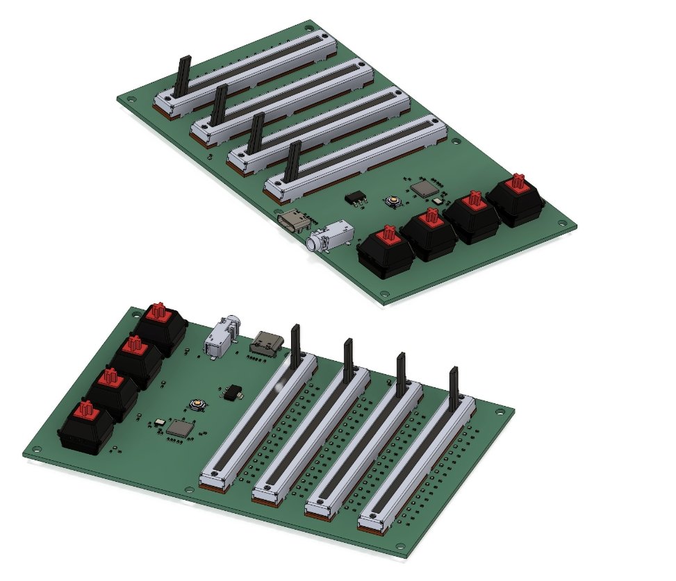
3D Renders
Enclosure
I usually go with a 3D printed enclosure made from PETG, but this time wanted to try the ol’ “PCB Front Panel” trick. I drew up a simple front panel in KiCad and included holes for all of the LEDs, Sliders, and Buttons. I thought they came out great, especially considering how cheap they are to get made. I used some brass standoffs to connect the main board and the front panel.
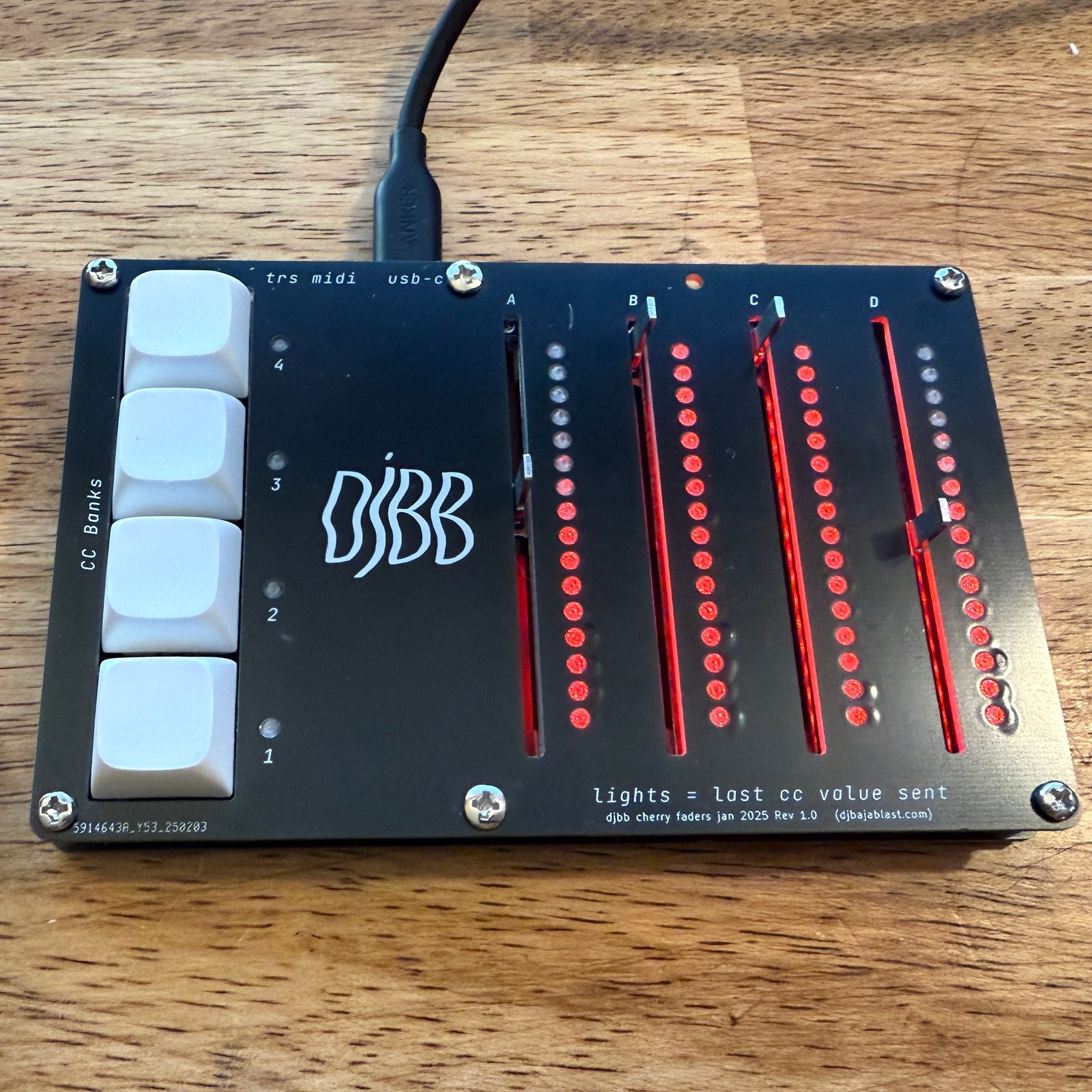
Assembled device with front panel and diffusers
The tiny LEDs shining through the panel holes were a bit harsh, so I designed little diffuser inserts and printed them out of transparent PETG, which did the trick. Note that the bottom layers are printed in black PETG in an effort to prevent too much bleeding between the pixels.
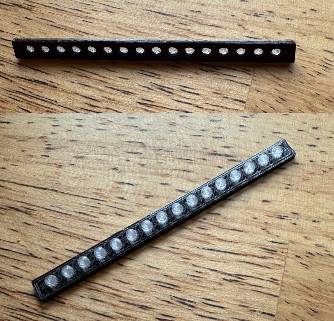
3D printed LED Diffusers
For the hell of it, I also created a nice Walnut case for one of them. I designed a router template in Fusion 360 and hand routed it out of a solid block of walnut. It was then hand sanded to a high grit and finished with a hardwax oil (Rubio Monocoat)
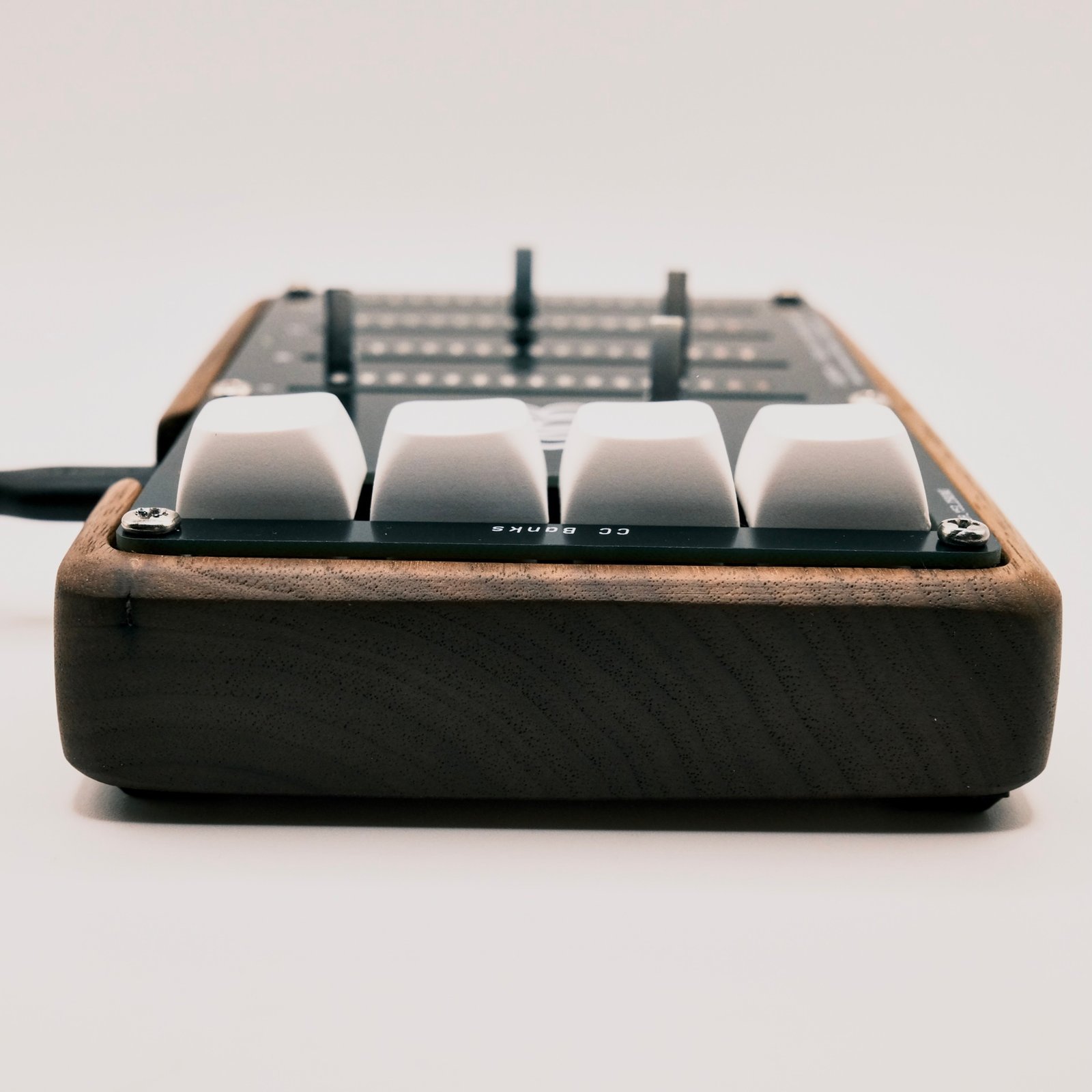
Walnut Enclosure