

Strange tape attempting to show you what it’s like to be schizophrenic. And some other random stuff that didn’t fit elsewhere.
Author: derrick

DJBB – Be Happy Attitudes Tapes
Guy talking about being happy and listening to god or w/e. You know the drill.

DJBB – Subliminal Stop Smoking Tape Sample Pack
Some samples from a “subliminal” tape aimed at smoking cessation. Some nice ambient biz as well.

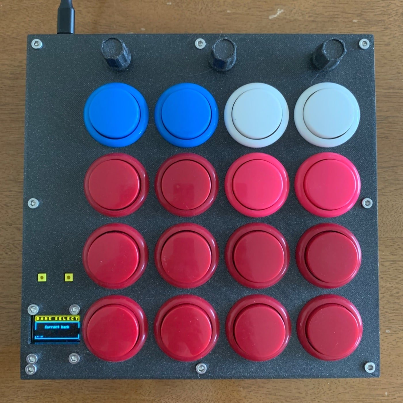
DJBB Arcade Button MIDI Drumpad
Features
- 16 (non-velocity sensitive) buttons for sending midi messages
- Preset midi banks that can be re-mapped
- Note: these mappings are per session. They will not be saved when the device powers off.
- Velocity control
- Repeat mode with optional note lock
- With free or BPM sync (ROUGH bpm sync, I should say)
Hardware / Tools
- (Tools) – Soldering Iron, Solder, M3 Allen Wrench, 3D Printer.
- 1 3D Printed case (models here)
- 1 Raspberry pi pico
- 1 SSD1306 OLED screen – (just google SSD1306 OLED and pick the one with 4 pins)
- 12 m3 nuts and bolts
- 12 m3 heat inset nuts
- Some wire (helpful to have some solid core as well – can solder the buttons together easily)
- 16 arcade-style buttons
- The shallower ones… like these
- 3 10k linear potentiometers
- 2 little clicky buttons for the screen controls (like these)
- 1 micro USB cable
Overall Cost (not including shipping, assuming Alibaba parts, super rough estimate): ~ $20-30 bucks?
Skills Required: Basic 3d printing. Beginner-intermediate soldering (we are using most of the pins on the pico so it gets crowded).
Note: you should test everything before proceeding, especially if buying these alibaba parts.
Assembly
- Insert the buttons and pots into the front plate.
- Use the M3 bolts to secure the screen, but DONT TIGHTEN TOO HARD. I cracked like 3 screens before I learned this lesson.
- Use a soldering iron to heat-inset the the m3 nuts into the bottom part of the case.
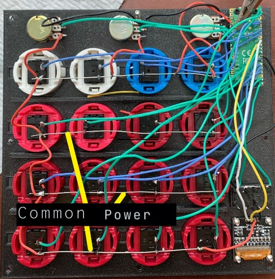
- Wire all of the button grounds together
- Here it is useful to use some solid core wire, completely stripped. You can snake this around and solder each ground pin to it. It then becomes a rail that you can solder the screen, pots, and control button grounds to as well (instead of using a bunch of different ground pins on the pico).
- Wire the buttons and pots to the board.
- Wire the screen to the board

picture of the wiring setup
Reference the raspberry pi pico pinout diagram (google it)
Buttons wiring
GP2 | GP3 | GP4 |GP5
GP0 | GP1 | GP8 | GP9
GP10 | GP11 | GP12 | GP13
GP14 | GP15 | GP16 | GP17
Pots wiring
Pot 1 (Left) – GP26
Pot 2 (Mid) – GP27
Pot 3 (Right) – GP28
Control Buttons
Btn Left – GP20
Btn Right – GP21
Screen
SDA – GP6
SCL – GP7
GND – Any Ground Pin
VCC – Pin 36 (power)
Operation
Plug it into your computer / iPad and look for midi devices in your DAW
Tested on MacOS, Windows and iPadOS
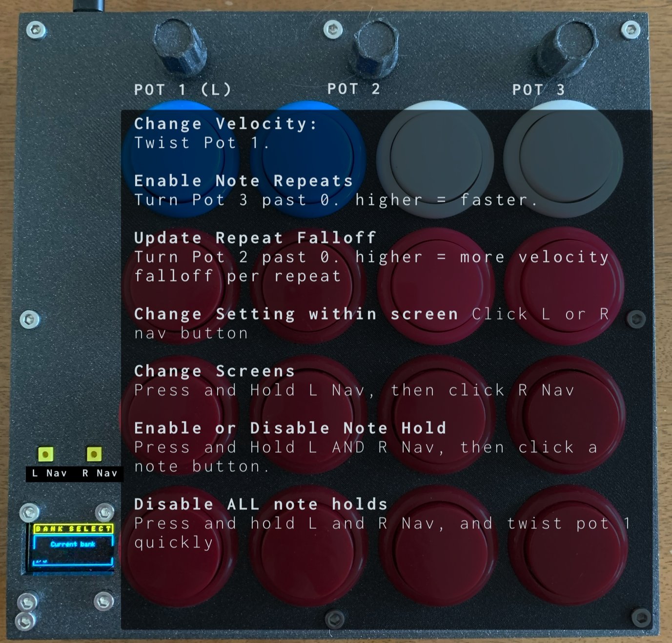
General Operation

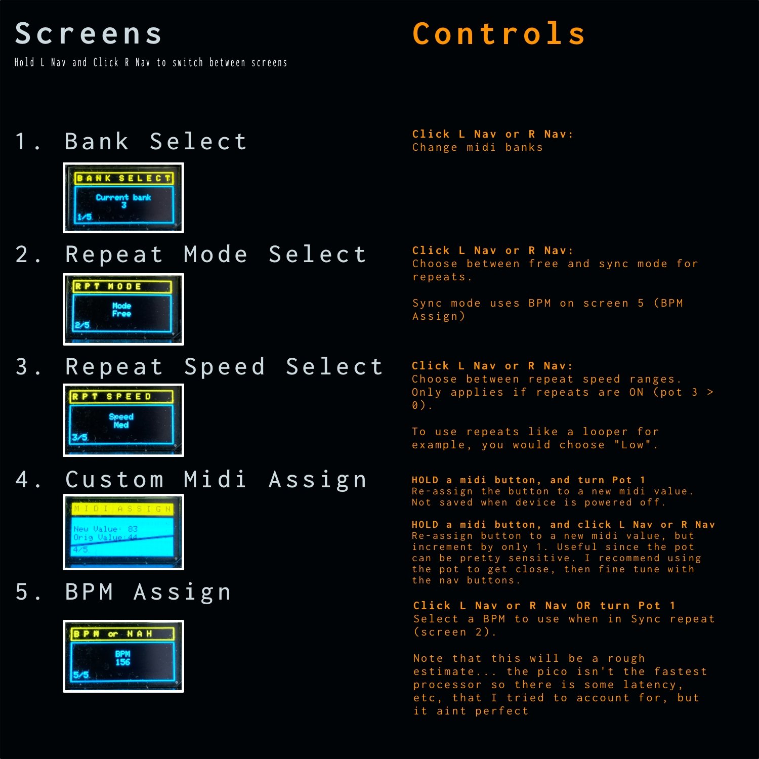
Screens Guide
Fun things to try:
– I created this to use with drums, but it can be fun with melodic stuff too. Try turning repeats on with repeat falloff set to 0 (Pot 2 all the way to the left).
– Now hold both nav buttons, and press a note button. It should now be repeating forever at the repeat speed (knob 3). Do this again with other notes to make a lil looper.
Software (Github)
- Perform setup as described here
- Add code.py and the lib folder from this repo to the base directory of your pico
- If you aren’t using the same screen as I noted above, you may have to alter code.py
You can open and edit code.py to your liking. I put some run options near the top of the file. These are constants that other parameters reference, so you can mess with these to easily change some of the general settings.
Enhancements and Optimization Ideas
- Some sort of preset system maybe? So saving custom mapped midi bank values, etc.
- More midi FX – Pot 2 is underutilized
- DAW BPM Sync? No idea if this is possible.
Not sure if it’s worth doing until this thing gets bigger and more unwieldy, but would be nice to..
- Refactor code into multiple files. Many of the constants could be separated into another file to make the whole deal easier to read.
- Run options, midi dictionaries, etc.

Create Your Own DIY Contact Mics for Cheap
While regular microphones pick up vibrations in the air, contact mics pick up vibrations in pretty much everything else. Clamp one to a tree branch, and you can hear rustling from the wind. Stick one to a thin sheet of metal, bang it, and you’ll get some fun alien noises. You can even attach it to an acoustic guitar or other acoustic instrument and get a relatively clean recording of what it sounds like in real life.
Contact mics are just piezoelectric elements hooked up to an audio cord of some type, like an aux cable. In summary you just need to cut 1 end off of an aux cable, strip the wires in the cable, solder ground and a signal wire to the piezo element, then repeat if you want stereo
Okay cool lets dive in and make our own DIY Contact Mics.
You Will Need..
- 1 x Audio cable (aux cord, 1/4″ guitar cable, etc.)
- 1 – 2x Piezo elements (just google “buy piezo discs” and get a cheap pack of them). If you want mono you only need one.
- Hookup wire
- Soldering iron / Solder / Flux
- (optional) Some way to encase / protect the final product. Anything from electrical tape to resin to custom 3D printed enclosures (which you can download models for free here)
Steps:
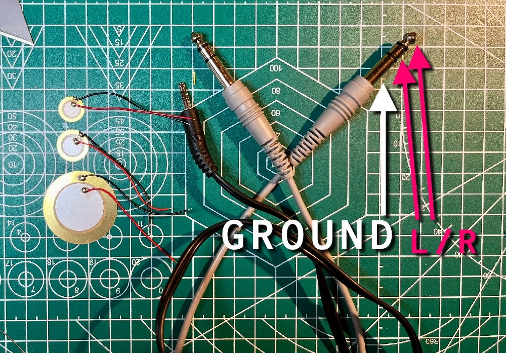
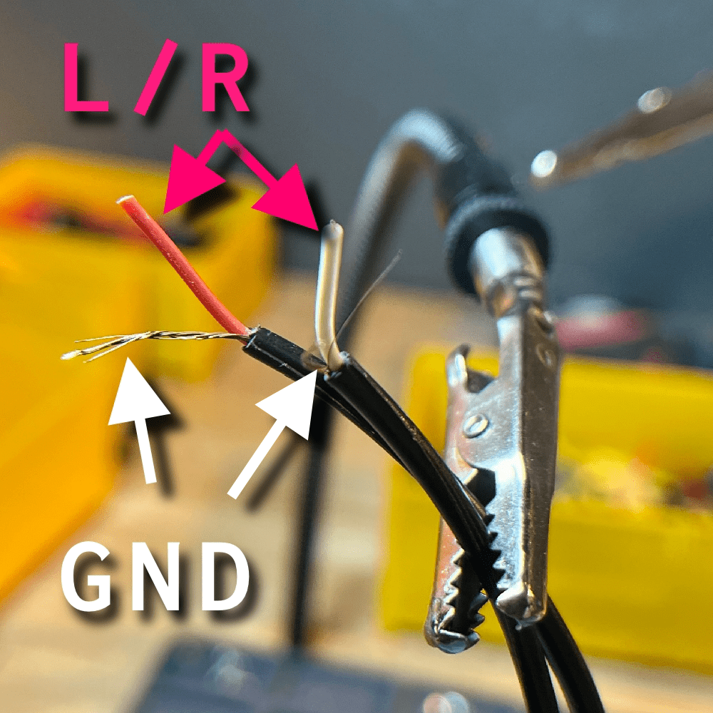
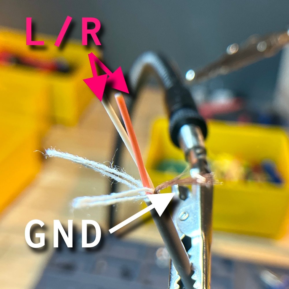
Strip your audio cable and determine which wire is ground.
For TRS (Tip Ring Sleeve – like aux cables and 1/4″ guitar cables) cables, ground is connected to the Sleeve part (furthest section from the tip).
Tip: Use a multimeter to check the resistance between a stripped wire and the sleeve section of the jack. The wire that reads something very close to 0 ohms resistance is your ground.

Here is an aux to RCA cable stripped.
Here is a 1/4″ TRS Guitar cable stripped.
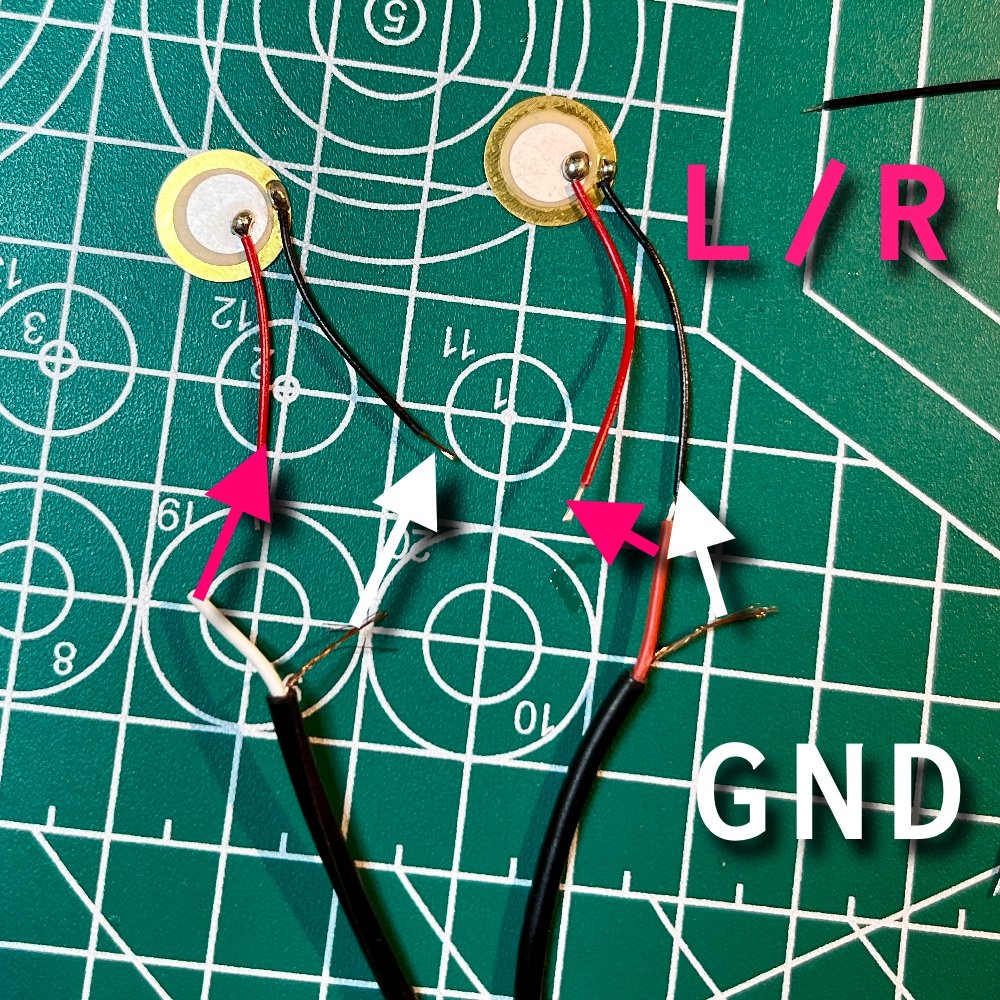
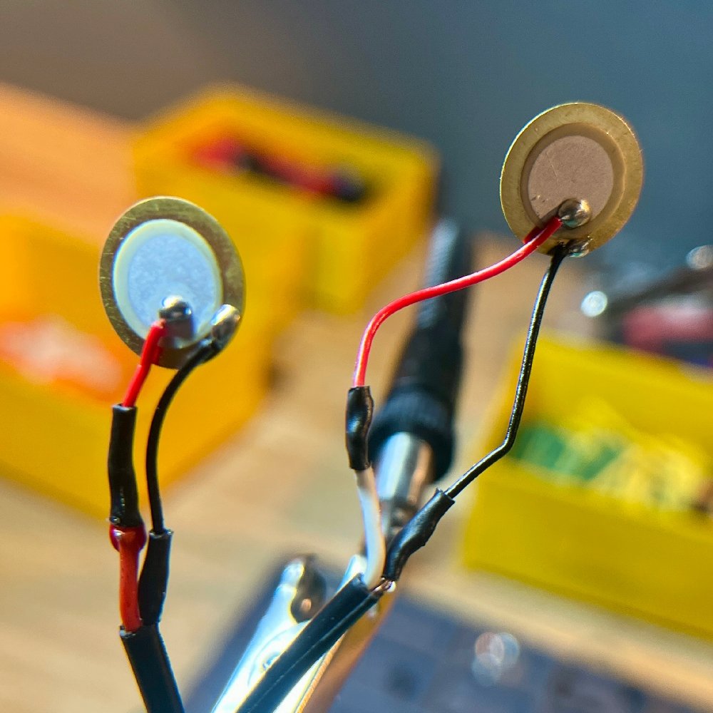
Solder the ground and L/R cables to your piezo elements. The outer ring of the element is ground. Mine had little wires pre-soldered.
Plug it in and make sure you are getting a signal.
And now you’re done! Problem is, these things are very delicate. So you’ll want to protect them in some way. At the very least, wrap some electrical tape around each of them. Or maybe glue them into a bottle cap or dip them in resin.
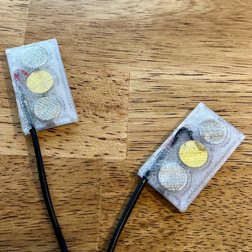
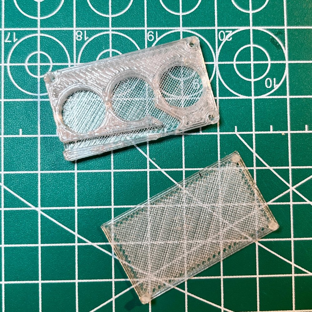
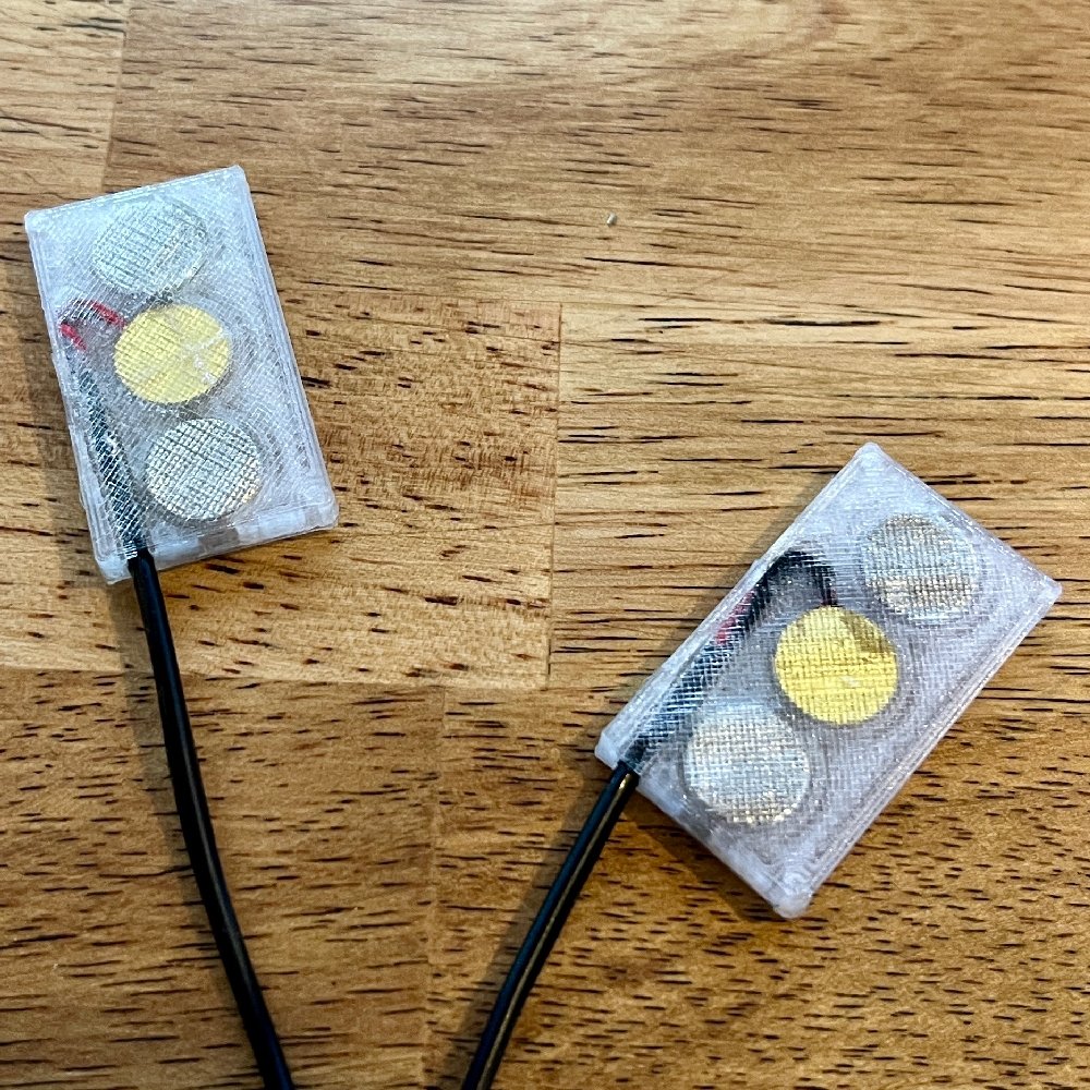
I opted for a 3D printed case since I have a 3D printer. I designed cases for a few standard sizes of piezo elements and magnets (these are fun to stick to metal so I recommend embedding magnets if possible). You can download them here.
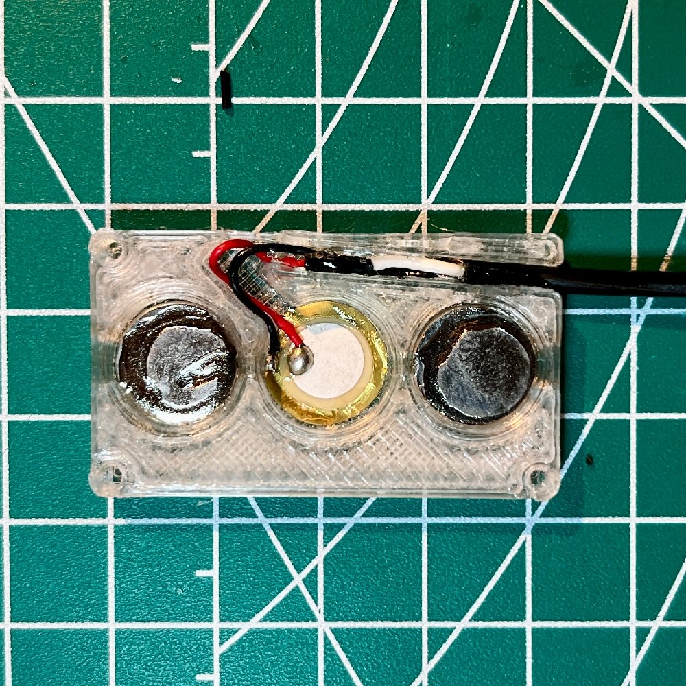
Super glue the piezo elements and magnets into place. Route the wire into the channel and glue it.
Pay attention to magnet polarity if you are making a stereo pair – it’s convenient for storage if they can snap together.
Now super glue the lid on and YA DONE.
Tips & Other Notes
- Aux to RCA cables are great – each channel has it’s own ground wire and protective sleeve.
- Try dipping the whole thing in resin to create a hydrophone?

DIY Passive Antenna for Recording Electromagnetic Sounds
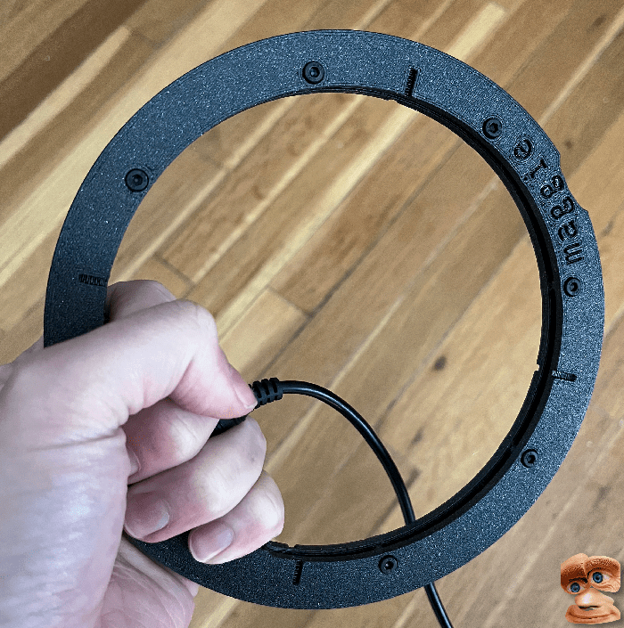
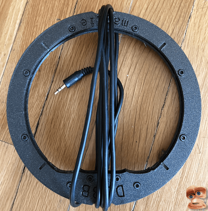
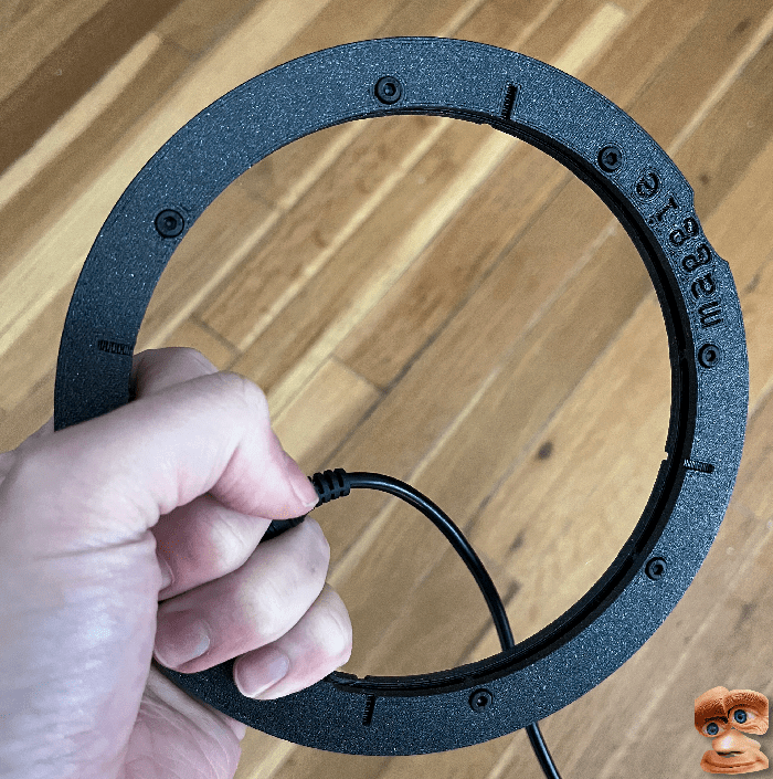
This is the DJBB Maggie – a simple device for listening to electromagnetic radiation in the world around you. Hold it up to your phone, computer, router, or anything with electricity to hear some interesting buzzes, bleeps, and the occasional radio or walkie-talkie signal. Similar to the Priezor LOM.

Finished DJBB Maggie – A Passive Antenna for Field Recording
Research & Audio Examples
I recorded audio from 4 antenna designs in the table below. I have a sample of the same source for each: holding it by a router, sweeping it around a Macbook, and holding a phone in the middle of it while opening apps and scrolling around. They were all recorded into my Zoom H1n with NO pre-amp, and the gain knob set to 7/10. They were all normalized and phase corrected before upload, but otherwise not processed.
The last test is a frankenstein coil made up of what I had left of a few different spools.
24 awg, 50 turns – Router, Laptop, Phone
30 awg, 300 turns – Router, Laptop, Phone
36 awg ,500 turns – Router, Laptop, Phone
36 + 32 + 30 awg, ~700 turns – Router, Laptop, Phone
You can download full quality files (24bit, 96khz) here
A super simple demo track with more examples
A free sample pack with sounds from these is hereYou Will Need..
- 3D Printer
- Soldering Iron + Solder
- Allen wrench for M3 Bolts
- Hot glue gun (Not strictly necessary, but good to have)
- Some all purpose glue or resin (hot glue, super glue, modpodge, resin, etc.)
- 3D printer filament (PETG or PLA) ~ 55 grams
- Download models here
- 10 M3 Nuts (8-32)
- 10 M3 Bolts
- 1 Aux jack STX-3000
- Note: I created my model to fit this just exactly. You’ll have to modify it if you use a part with different dimensions.
- Magnet Wire*
- I suggest 32 AWG
*Note on Magnet Wire I tested with a few gauges, and I suggest 32 AWG. I would not go larger than ~30 AWG, but go as small as you’d like.
Larger (lower AWG number) = Fewer
Assembly:
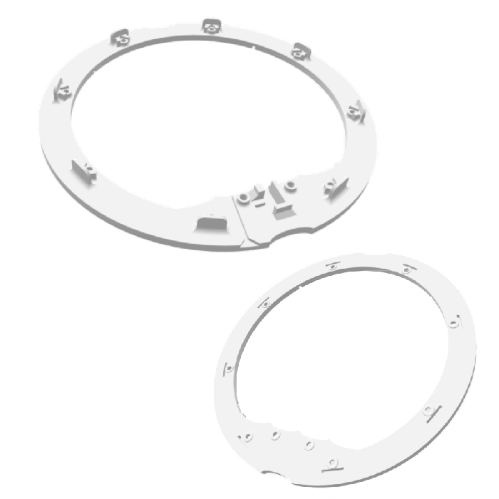
3D print the top and bottom piece. I used PETG and a 0.6 mm nozzle, but anything should work. models here.

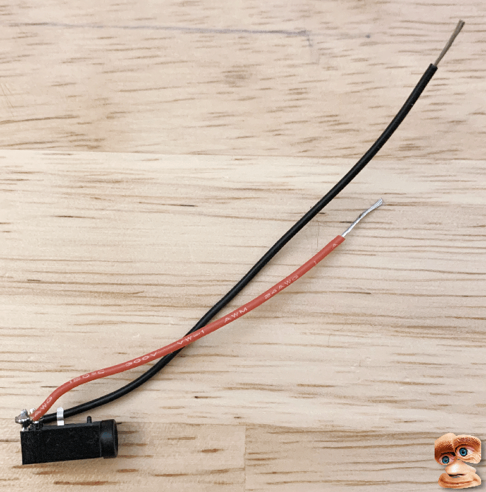
Cut 2 pieces of wire – about 15 cm.
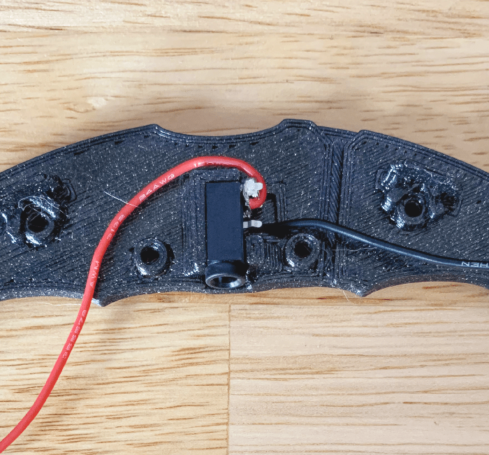
Solder these wires to the L and R pins on your aux jack. These are the 2 pins on the bottom of the jack. The single in in the middle is ground, which we don’t need.
NOTE – You could also skip the aux jack and solder an aux cable directly if modularity isn’t important to you.

Pop the aux connector in its home, and route the wires like so.

Snap on the other shell, insert the nuts into their inset holes, and screw it together.

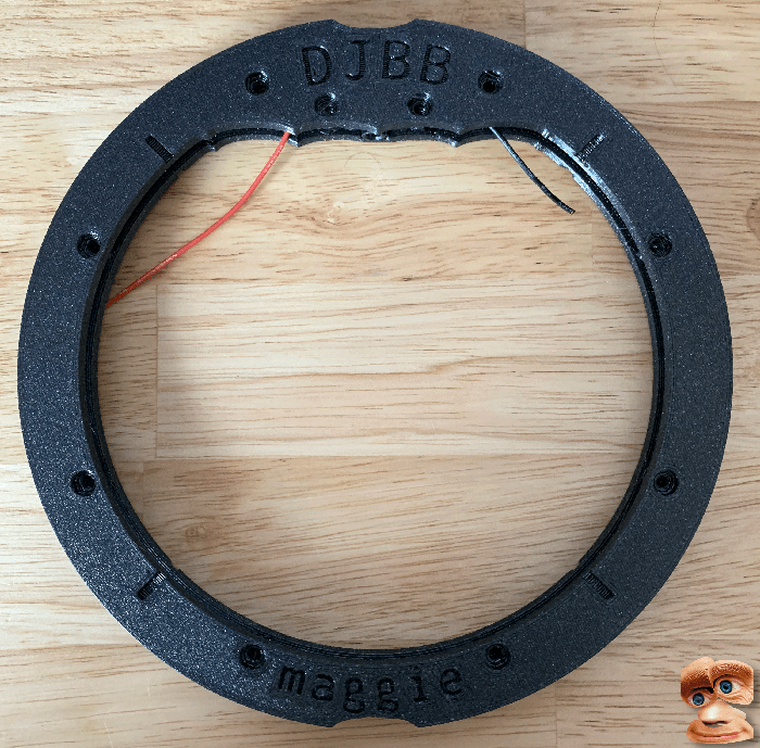
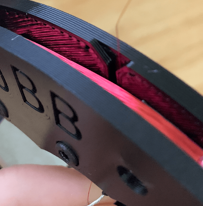
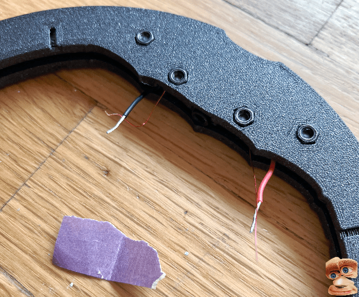
Wind the magnet wire around the shell. You want the two ends to terminate near the 2 aux jack wires.
Note the little channel that can be used to get the top coil wire back down to the aux jack wires.

Use a small piece of sandpaper to sand off the coating on the two ends of the magnet wire (so the solder sticks).
You may have success melting it off with a hot soldering iron instead, but I never did.

Shove the soldered wires into the space within the shell. Secure with hot glue, or whatever you have.
Apply hot glue, resin, superglue, or whatever to the outside of the wire windings to hold everything in place. You don’t want the wire to unwind somehow.
Plug in your aux cord and you’re ready to go. Plug it into a pre-amp -> audio recording device if you can, but it also seems to work by plugging straight into something like a Zoom H1 and turning the gain up. This is what I usually do.
Notes, Enhancements, Ideas
One very important thing to note is that this thing produces stereo audio that has extreme phase issues. YOU MUST FLIP THE PHASE OF ONE OF THE CHANNELS after recording.If you don’t, it’ll sound neat in headphones, and absolutely silent in mono. There is probably another way to wire it to avoid this issue, but I haven’t experimented with that yet.
Here are a few ideas of things to try recording:
- Wifi router
- 3d Printer
- Laptop
- Smartwatch
- Telephone poles
- Cars passing by on the road (really crank the gain)
- Electrical boxes on the side of the road
- Anything using electricity
If you’re into DIY audio devices like this, perhaps check out my guide on making a pair of contact mics.
And there you have it. Your own lil’ thing to record electromagnetic sounds for not-too-much-money.

Cassette Player Speed Control Mod: Adding a Simple Speed Control to (almost) any Cassette Player
Background
Most cassette players do not have a speed control function, but thanks to the design of (most.. probably all but don’t quote me) tape players, it is easy to add.
Cassette players have a trim potentiometer (also known as a trim pot or trimmer), which is used to fine tune the speed of the motor when being assembled. Trim pots are variable resistors – their resistance can be set by twisting a little screw. If we replace this component with our own variable resistor in the form of a twist potentiometer and then place it on the outside of the tape player, then we can control the speed of the motor on the fly by simply twisting a knob.
So grab your tape player and lets do it!
You Will Need..
- 1 x Tape player
- 1 x Twist potentiometer or slide potentiometer (in the 10k – 20k range. Most common ones should work)
- Hookup wire
- Soldering iron / Solder / Flux
- Small screwdriver(s)
Steps
!! Only use low voltage battery operated units unless you know what you are doing (no wall outlet voltage = much safer) !!
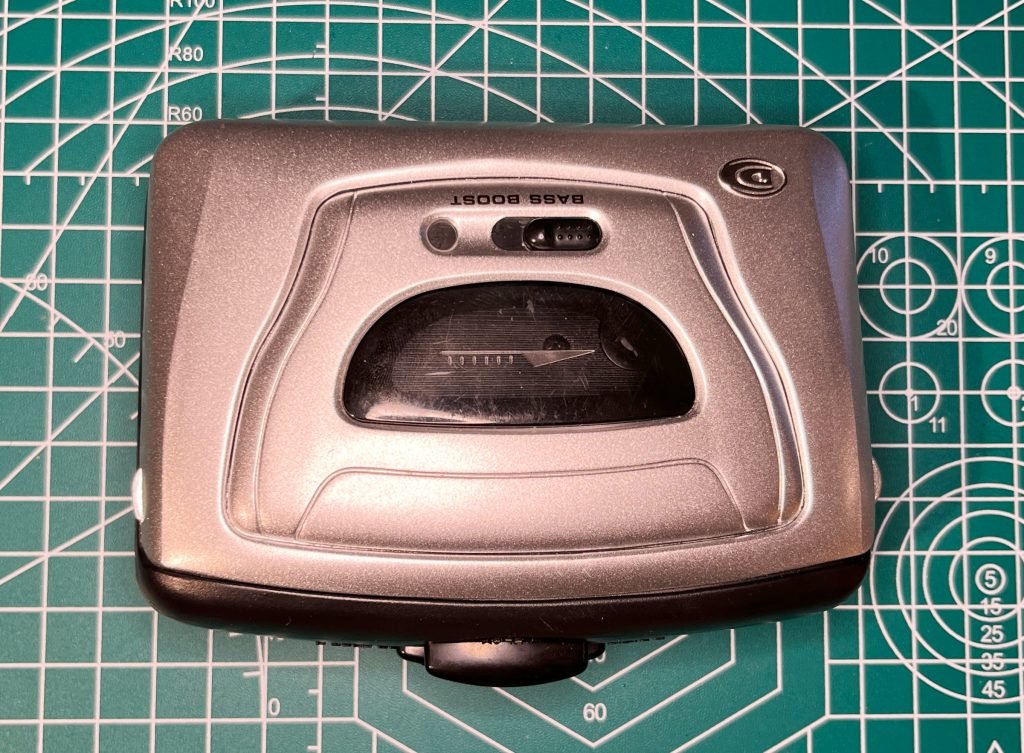
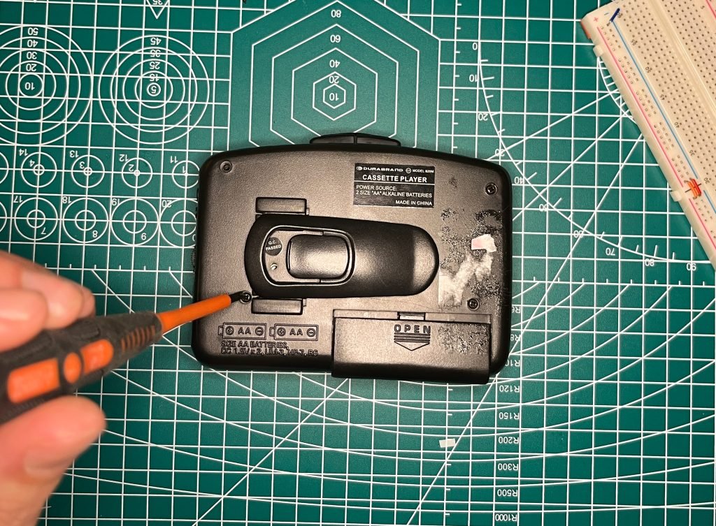
Obtain a tape player. This one was from the thrift store. REMOVE THE BATTERIES.

Unscrew the case. You may need to peel up rubber feet / remove clips / etc.
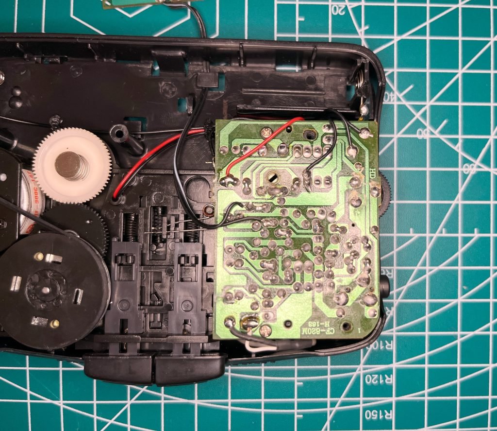
Find the main circuit board. If you don’t see a trim pot (see next few steps), then unscrew the board and flip it over.

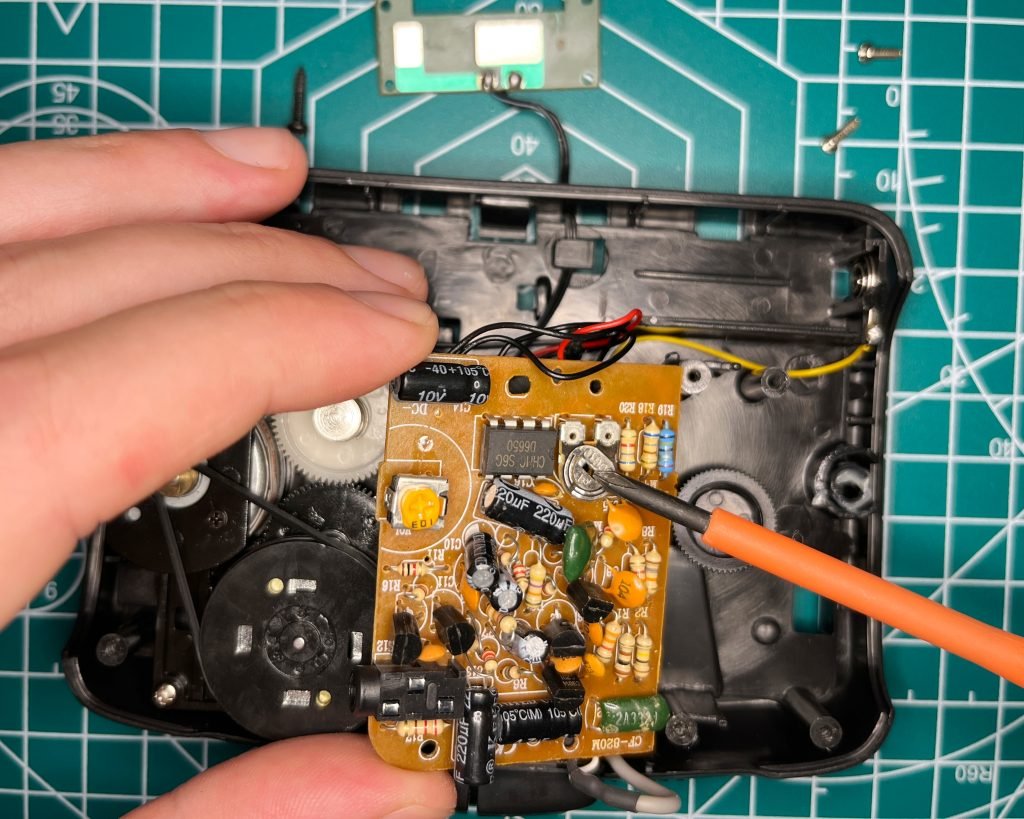
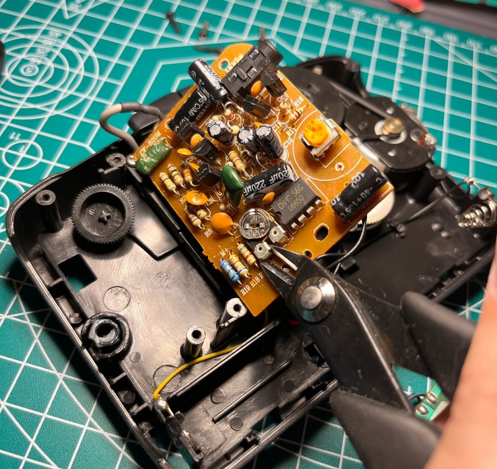
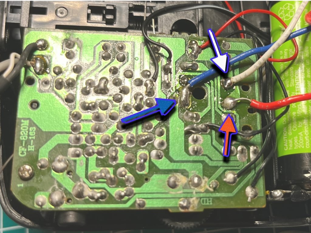
Locate the trim pot. This is a variable potentiometer used to tune the speed of the motor at the factory – aka a built in way to adjust the motor speed. We want to remove this and replace it with a normal twist or slide potentiometer to make it easier to adjust on the fly.

Clip the trim pot from the board, or desolder it.

Locate the solder points for the trim pot on the back of the board. Solder one wire to each (3 in total).
TEST: Temporarily re-insert the batteries and press play. The motor should spin at full speed if all went well. Test shorting the wires together. Some combination should either stop or slow the motor.

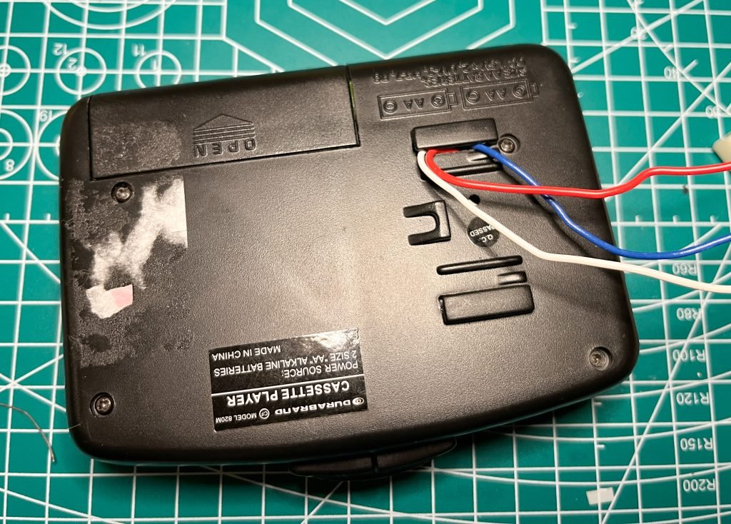
Find a way to feed the wires back out of the tape player and re-assemble. You may need to drill a hole. I got lucky with these holes for the clip on the back.

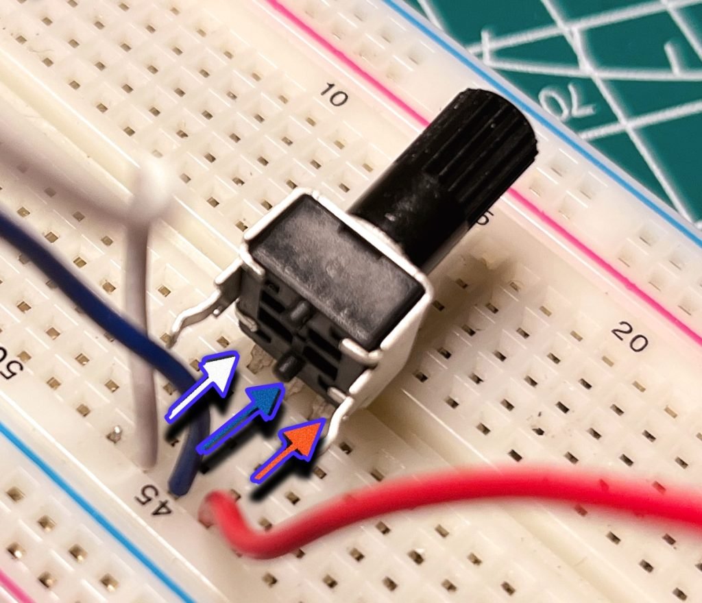
Attach the three wires to your potentiometer. The trim pot had 3 connectors: 2 on one side, and 1 on the other. Connect the one on a side by itself to the middle pin of the potentiometer. (blue wire in my case).
NOTE: If you don’t want to think about it, just try all of the combinations until the twist pot controls the speed.

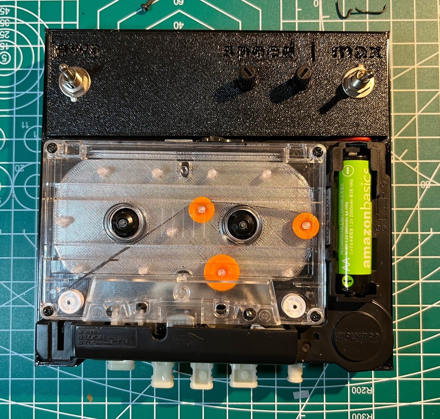
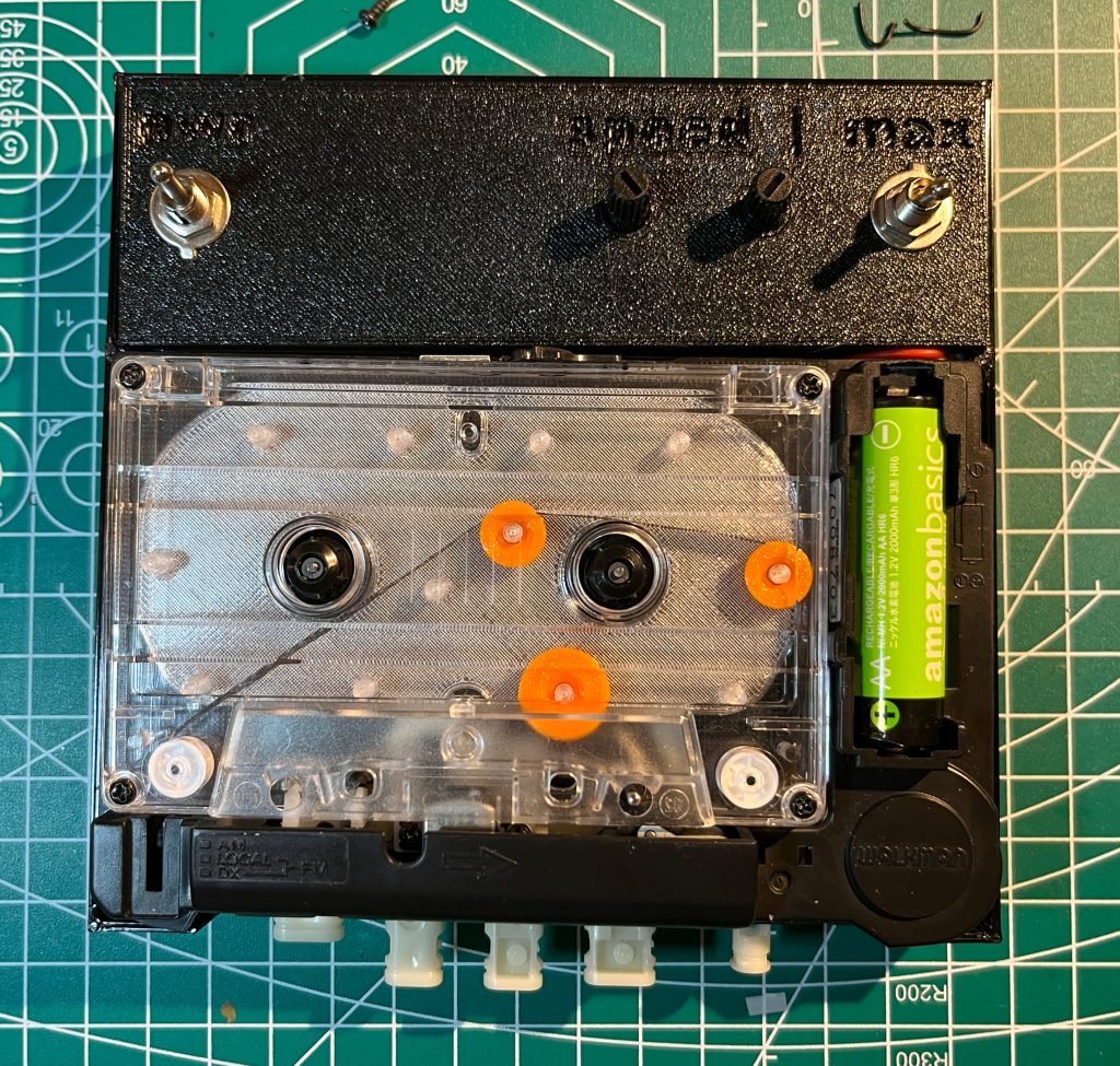
You’re done! Here is one I built and 3D printed a case for to house the controls. This one has 2 twist pots in series (messing around trying to get better control), an on/off switch for the whole player, and a “max speed” switch to completely bypass the speed control.

You’re done! Here is one I built and 3D printed a case for to house the controls. This one has 2 twist pots in series (messing around trying to get better control), an on/off switch for the whole player, and a “max speed” switch to completely bypass the speed control.
Tips & Other Notes
- Insert the batteries and test often to make sure you didn’t break something.
- For portable style tape players like mine, you usually don’t need the front clamshell at all. In both of mine I snapped it off to get that open-faced look.
- If you are using an old tape player like me and have issues with it not having enough power to play a tape, your belts might be the issue. Google “cassette belt kit” and you should find cheap packs of them.
DJBB Electromagnetic SFX 2.0
Electromagnetic noises collected with a custom (open source – make your own) antenna
DJBB – A Typical Day as the New You Sample Pack (Cassette, spoken word)
Words and phrases ripped from an 80’s motivational tape set. Calmly learn how to eat healthy foods and feel good about yourself, or whatever.




![DJBB – Unclear! [2.xtra – beginnings and endings]](https://djbajablast.com/wp-content/uploads/2026/06/bcb2d9d253f5.jpg)