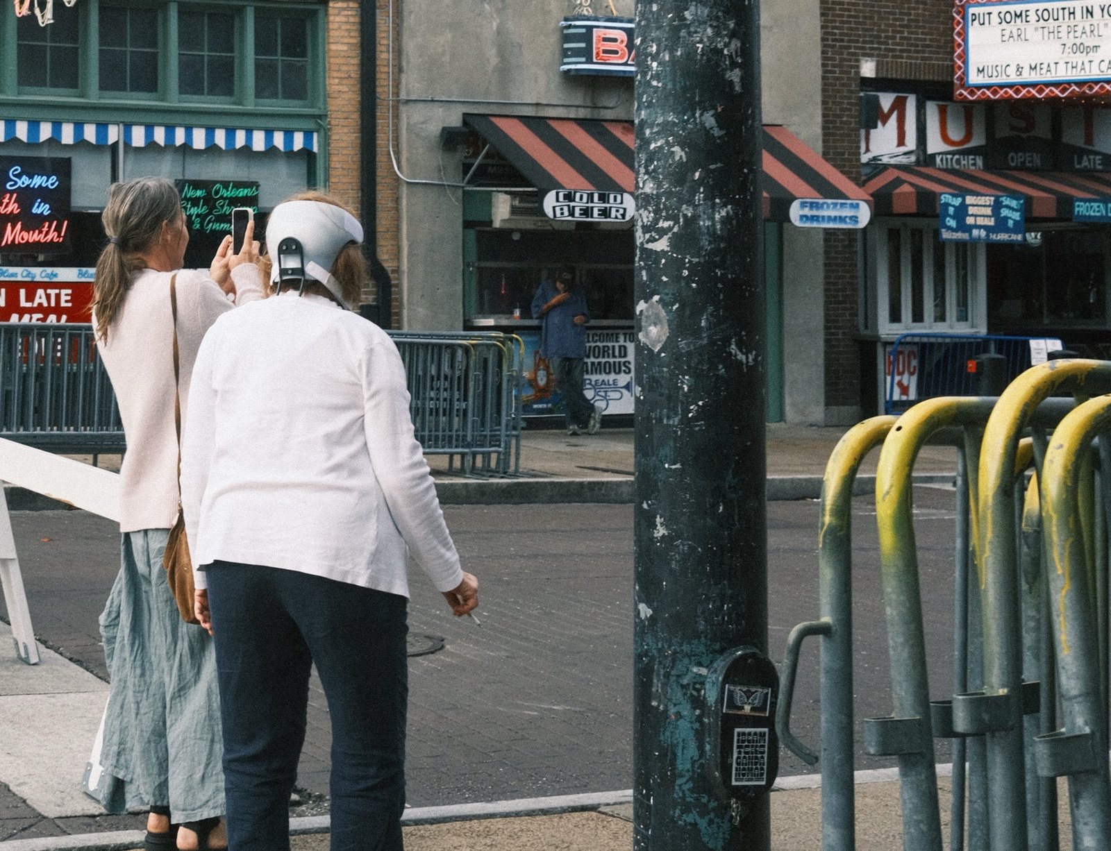
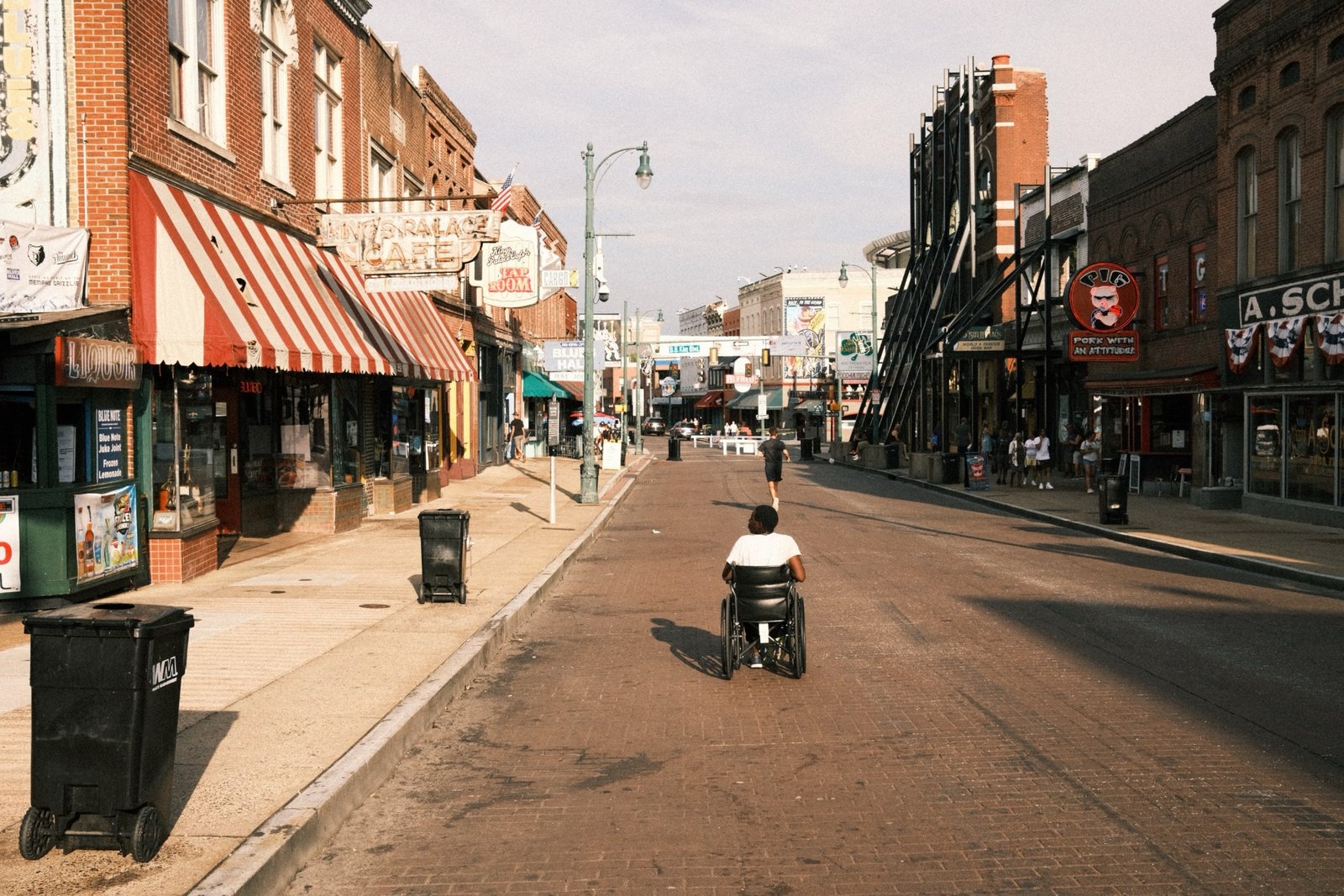
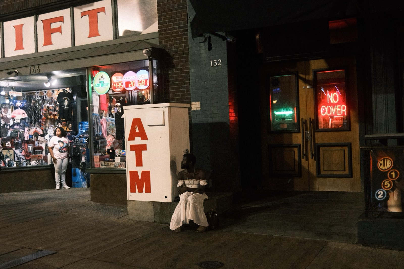
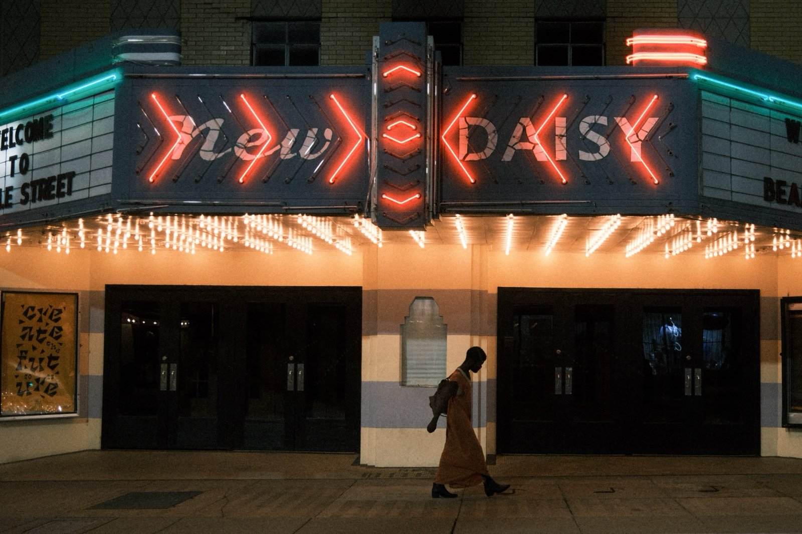
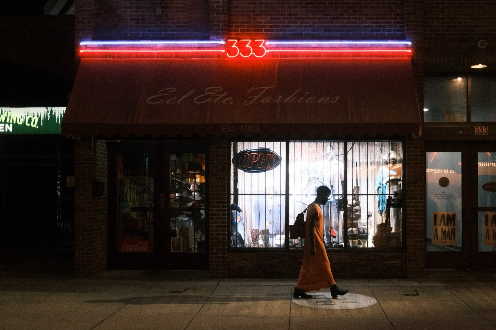
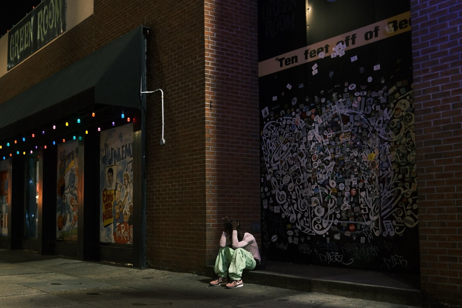
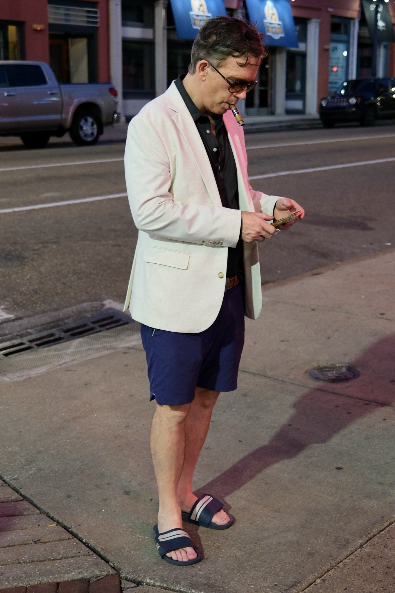
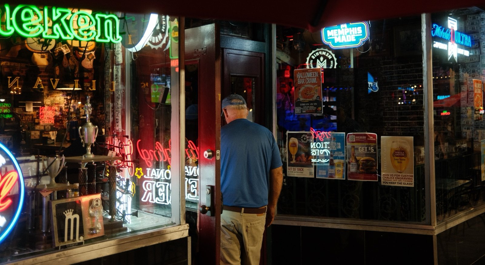
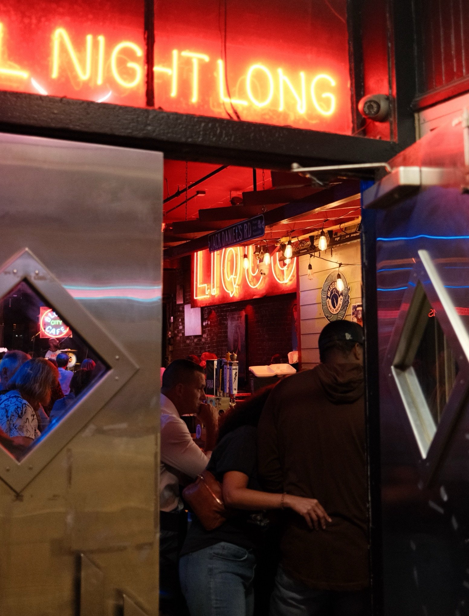
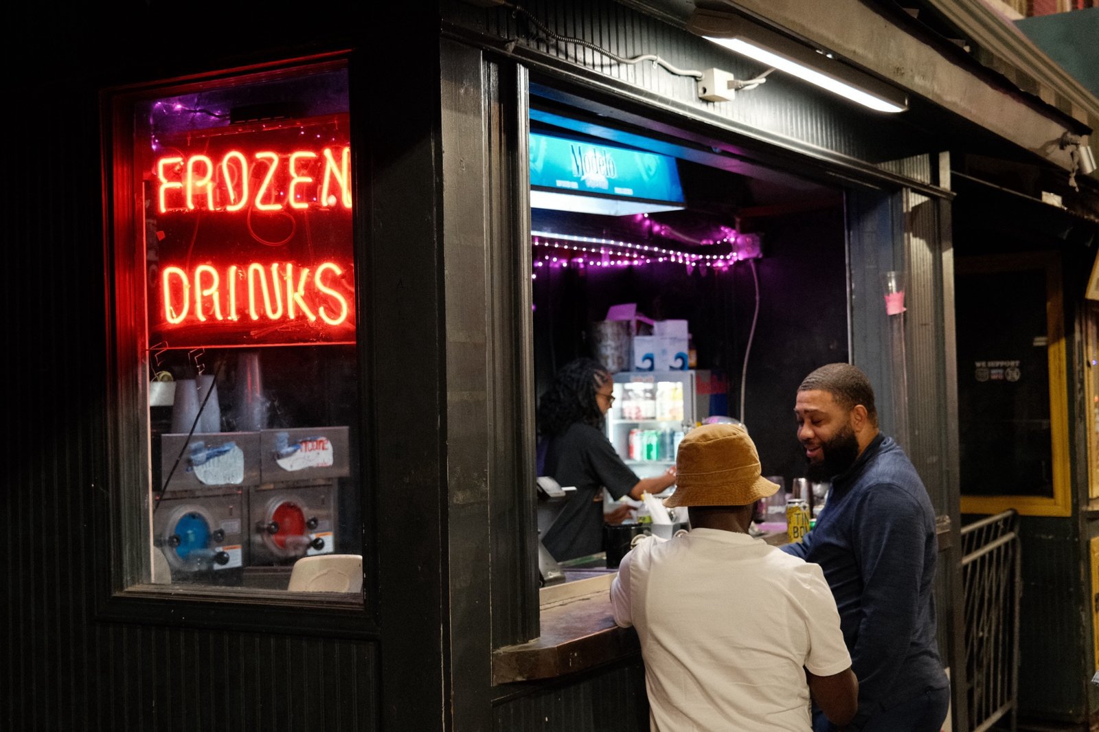
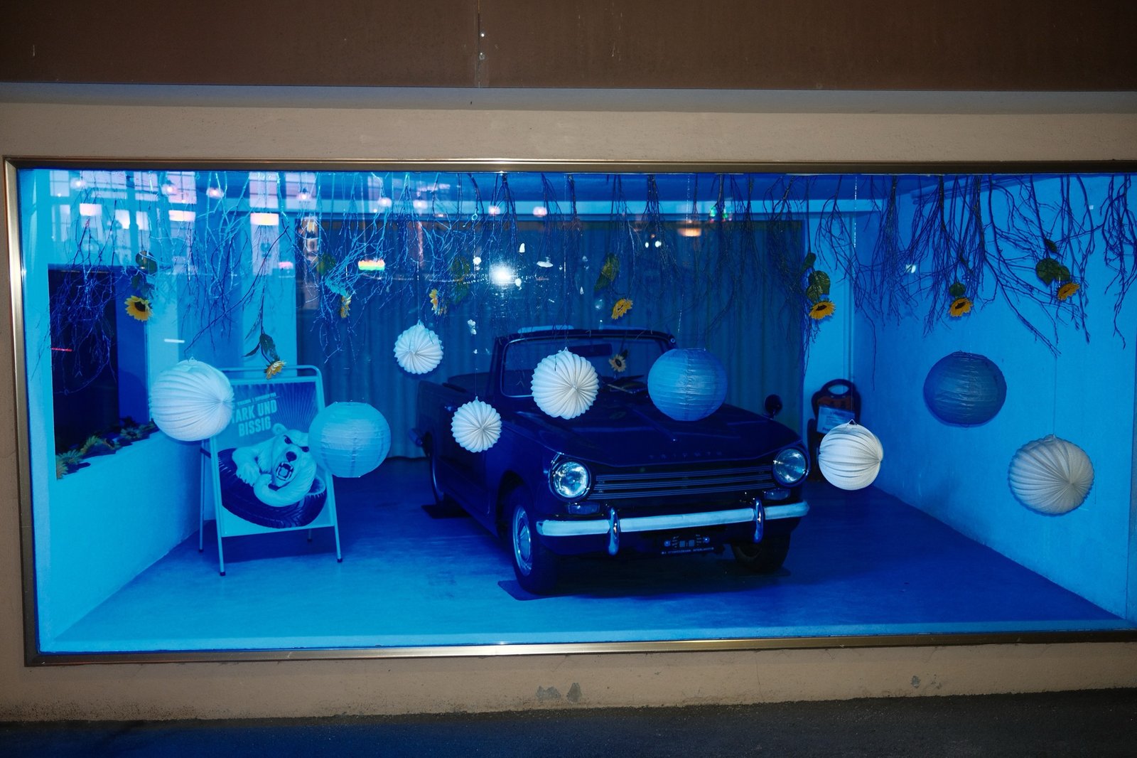
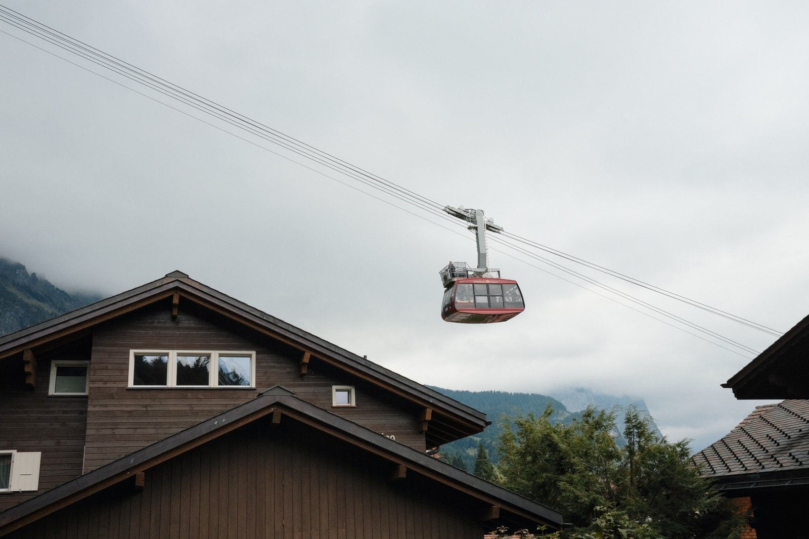
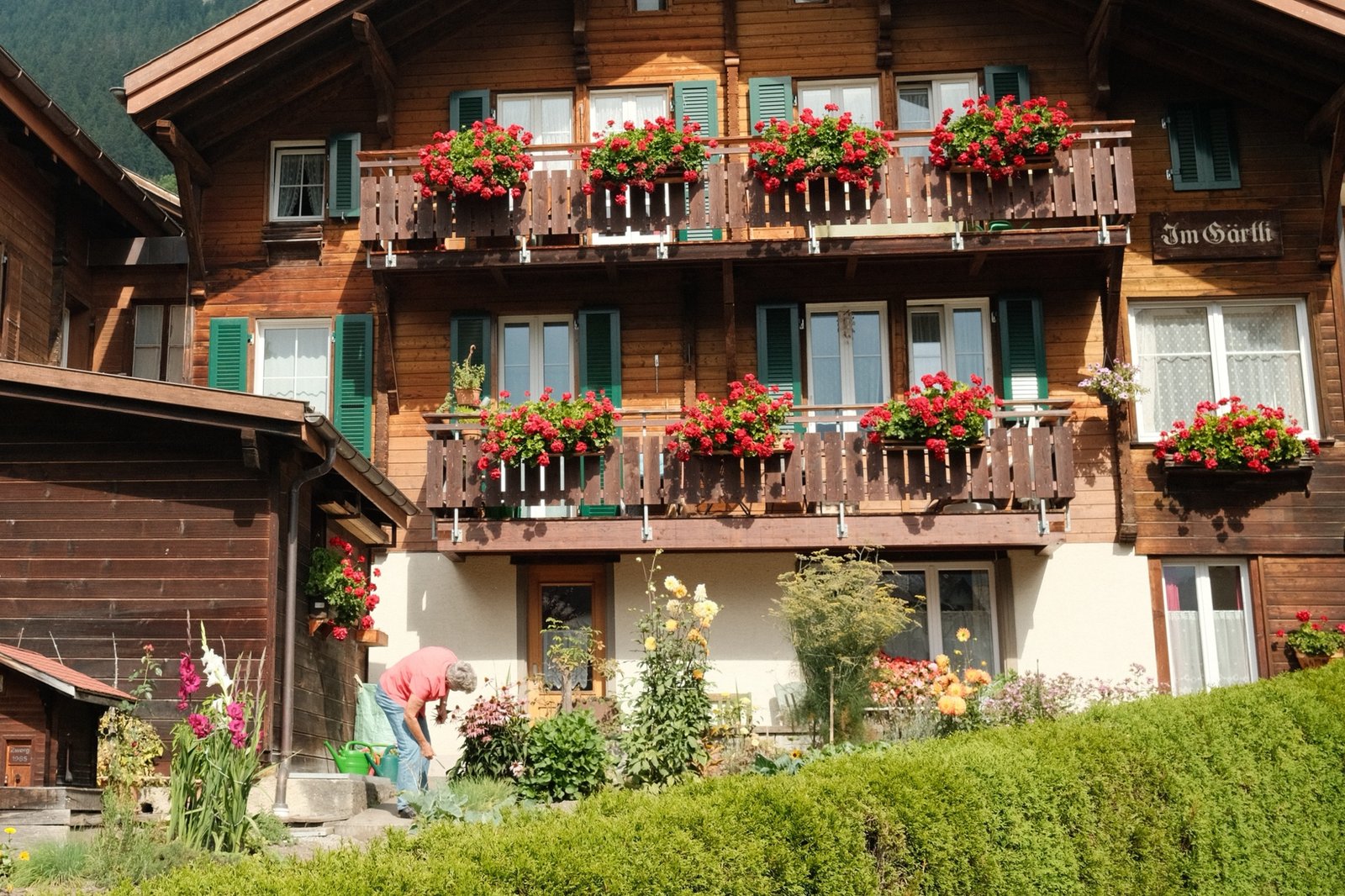
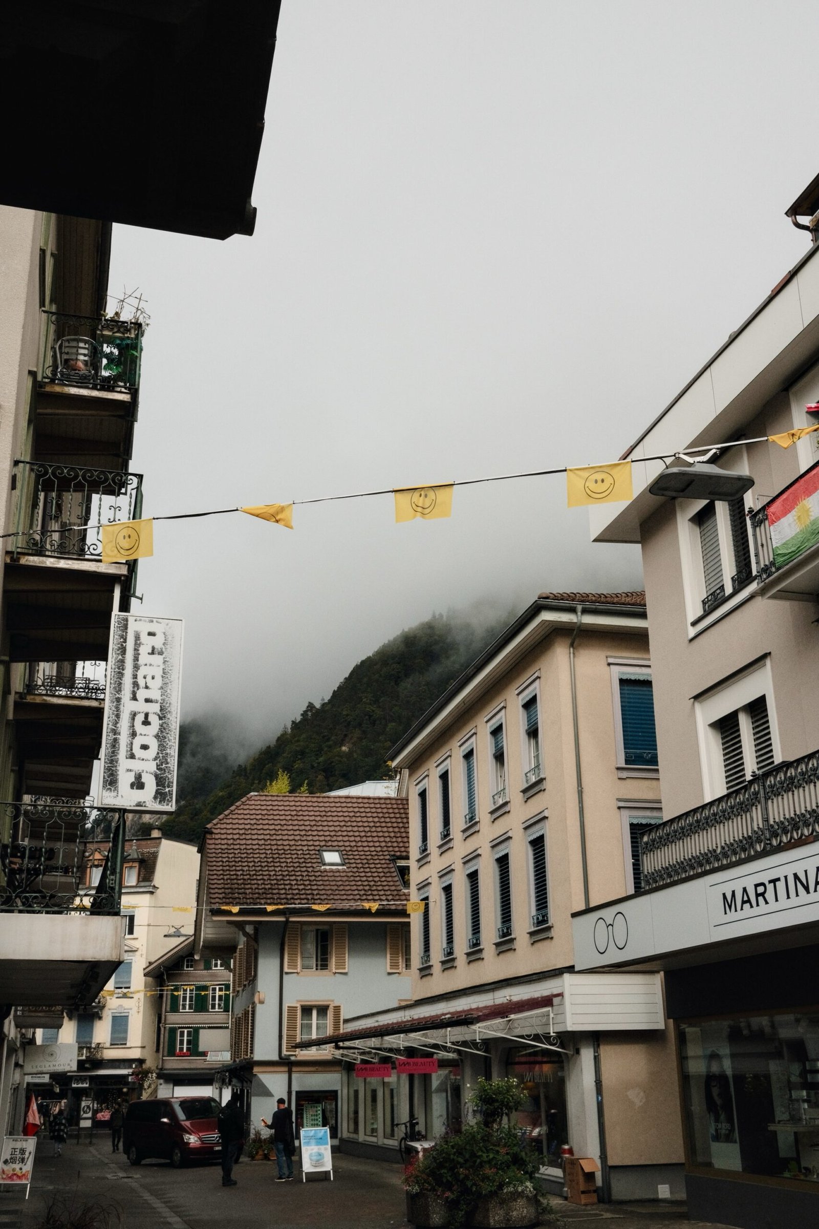
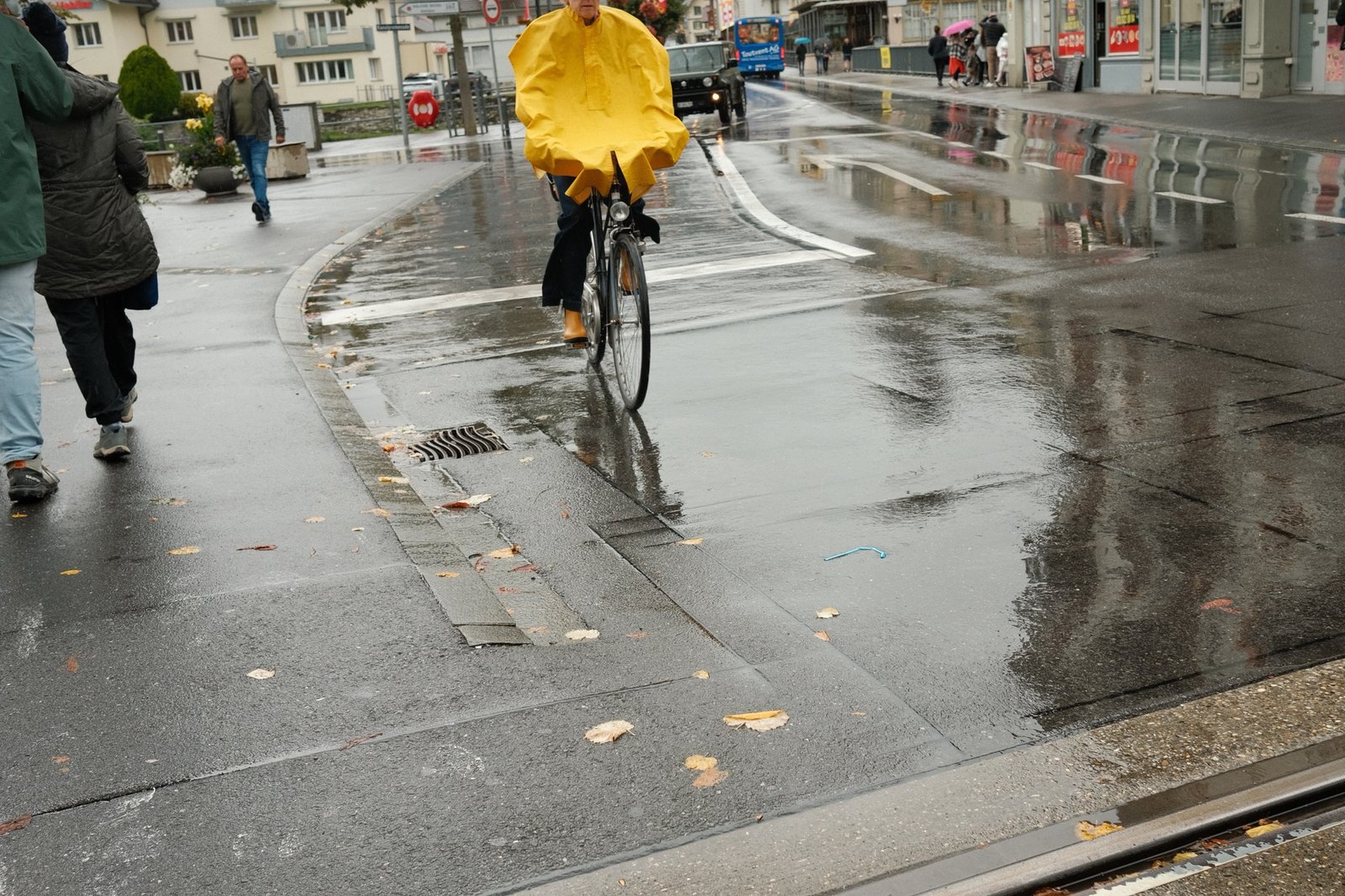
I’ve been going to Memphis, TN for work at least once a month. My hotel is within walking distance of Beale Street, and turns out, it has a lot of characters. Here are some of the people also wandering around. One particular guy appears in many of the photos. As a disclaimer that I’m not THAT big of a creep – these were over like a 1 year period.
I’ve been going to Memphis, TN for work at least once a month. My hotel is within walking distance of Beale Street, and turns out, it has a lot of characters. Here are a handful that capture the vibe of Memphis and Beale Street in particular on mostly Tuesday + Wednesday nights in 2024.
For instructions on installing the new firmware, download the manual above.
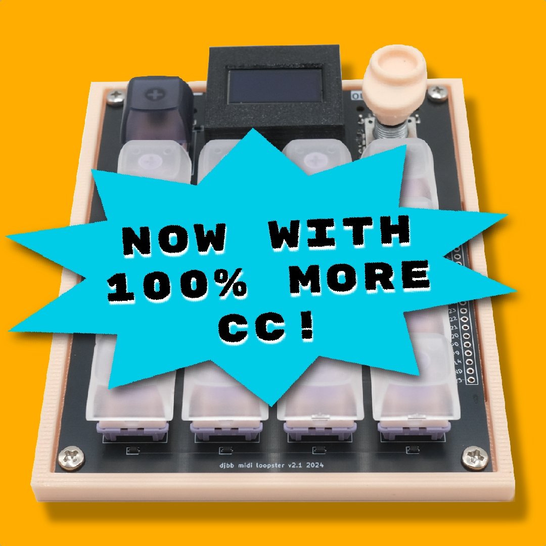
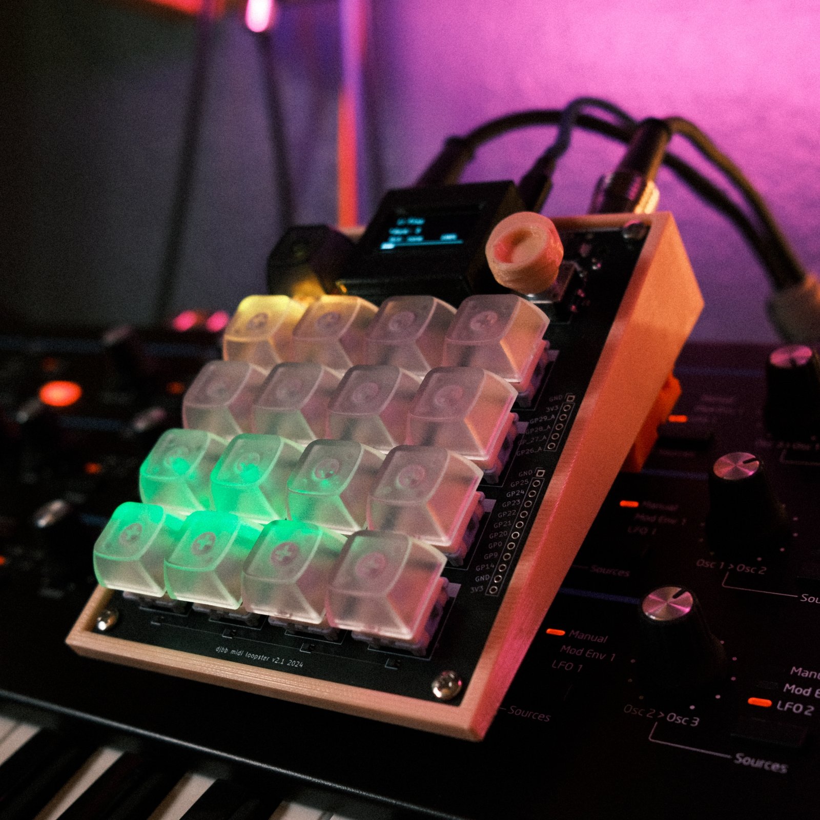
I’ve been working on this update for quite a while. First the issue was scope creep – I kept adding in new features that popped into my head. The second issue was testing all of this again. I refactored most of the code (again), which in addition to all of the new features, created bunch of new bugs to squash. I also battled memory issues – CircuitPython is not the most efficient, and the RP2040 does not have much “oomph”. Thankfully, a majority of these problems were solved by just changing the way that scales are generated – creating them all at once made for a very large list of lists which is not very RAM friendly. Now, it only generates them when selected.
SMD Components – can get it partially assembled at the factory
RP2040 chip built into board – no more raspberry pi pico needed
RGB LEDs for buttons for user feedback
Full sized MIDI In and MIDI Out in addition to USB midi
Button matrix to use fewer GPIOs
Unused GPIOs broken out to headers
Add your own sliders / buttons
Control a strip of neopixels
Audio out via PWM
Slanted case design
New Features:
Arpeggiator – hold buttons and turn encoder
Save / Load user presets
save scale, starting screen, arp settings, MIDI channel, etc.
Quantize chords and loops
MIDI In Sync
BPM
Start / stop messages
Record MIDI In to loops / chords
RGB LEDs for user feedback
Recording pad blinks red, etc.
The problems I aimed to solve with V2 were mainly:
Make it easier to produce: I sold 5 units and a handful of kits of V1 and realized that it took me too long to assemble everything. I intend to sell this one as well, and want it to be fairly inexpensive.
Better MIDI features: TRS MIDI is annoying and we all know it. I wanted to be able to plug this directly into a synth without worrying about grabbing the right converter cable (or buying a new one)
Figure Out MIDI In: could have done this with USB MIDI in the last version, but that didn’t sound as useful as DIN MIDI In. I wanted to plug a MIDI keyboard into the Loopster and use it to record some loops and chords.
Better User Interface: I could only do so much with the little screen, and on top of that, it was CPU intensive to update.
Design Process
I don’t feel like going into detail about everything, and you can find better tutorials elsewhere anyway. I’ll focus on specific things that I learned.
Schematic / PCB Design
I don’t have a ton of experience with PCB layout and design – pretty much just the projects you see on this website that involve it. I was nervous about stepping it up so hard by embedding the raspberry pi Pico circuit directly into the board, so I settled on designing just a clone of the RP2040 for practice. But then I thought nah, let’s do it live.
The Raspberry Pi Hardware Design document was super thorough and easy to follow. It uses very common components, all of which JLCPCB had in stock. I had never done anything this close to this complicated and it worked after just a few modifications which have since been fixed on the PCB – keeping track of MIDI pins is hard :/. Either the lesson is that I experienced a miracle, or that you shouldn’t be afraid to try the same, even if you are a beginner like me.
BUTTONS
My main criteria were:
Satisfying to push (not mushy)
Relatively quiet (no arcade buttons)
I settled on cherry-style keyswitches that are fairly linear (aka not the super clicky “blue” ones.
DIN MIDI
A lot of folks don’t use USB midi. The old design used mini TRS for a midi out solution, but had no midi in. I knew I wanted to use full sized DIN midi ports, in and out. I have never messed with midi in, but it wasn’t too difficult to figure out. This website is super helpful
I messed up the pins on the first try – it’s super easy to confuse the orientation. Thankfully it wasn’t a critical mistake and using little jumpers helped to fix it. this cheat sheet is the best.
SCREEN / NEOPIXELS
I wanted to add features to the loopster, but needed a better solution for a user interface. Doing more with the SSD1306 OLED screen was a non-starter, as it’s too slow to update can’t have 200ms pauses when sendn MIDI notes. I landed on Neopixels under each key, the select button, and the encoder. Neopixels are great because they only take up one GPIO pin, regardless of length. They are also dirt cheap and there are libraries for using them for everything at this point. I could use multiple colors to emphasize to the user what is going on (button flashing red = recording, etc.).
The neopixels seem to run fine on 3.3 volts – I have always done this without a problem so I wasn’t worried too much.
Hardware lessons
Be careful about DIN MIDI Pinouts – whether you are looking at the male or female view matters
Break out unused pins to a header on the side, cause why not
Always use the “dumbest” pin possible when assigning inputs / peripherals to pins.
Try not to use a SPI pin if another digital pin with no special features is available
Don’t use analog pins for digital things unless you have to
Put white silkscreen under LEDs to bounce light up
Software Lessons
When using Python… use more classes. Even if it seems kinda dumb at the time.
Use GitHub more. Adding enhancement requests / issues to my own repo was super helpful for documenting and tracking.
Use a “globals” file or some file that can be imported everywhere to avoid dealing with circular dependencies.
Resist the urge to optimize – I made bad design choices to save on performance, but who knows if it even would have mattered. Better to ignore until it’s a problem.
Keep modularization in mind the whole time. I refactored like 3 separate times because things would get unmanageable due to me not considering that some things would need to be used elsewhere in the future.
AI is kinda nice. I resisted using it for whatever reason, but it does a great job with writing small Python functions and documenting code. Things that you know how to do, but are not interesting and take more time than you’d like.
The last 10% takes as long as the first 90%. I swear I was almost done months ago… but kept finding small bugs and edge cases, and things that weren’t behaving as I wanted.
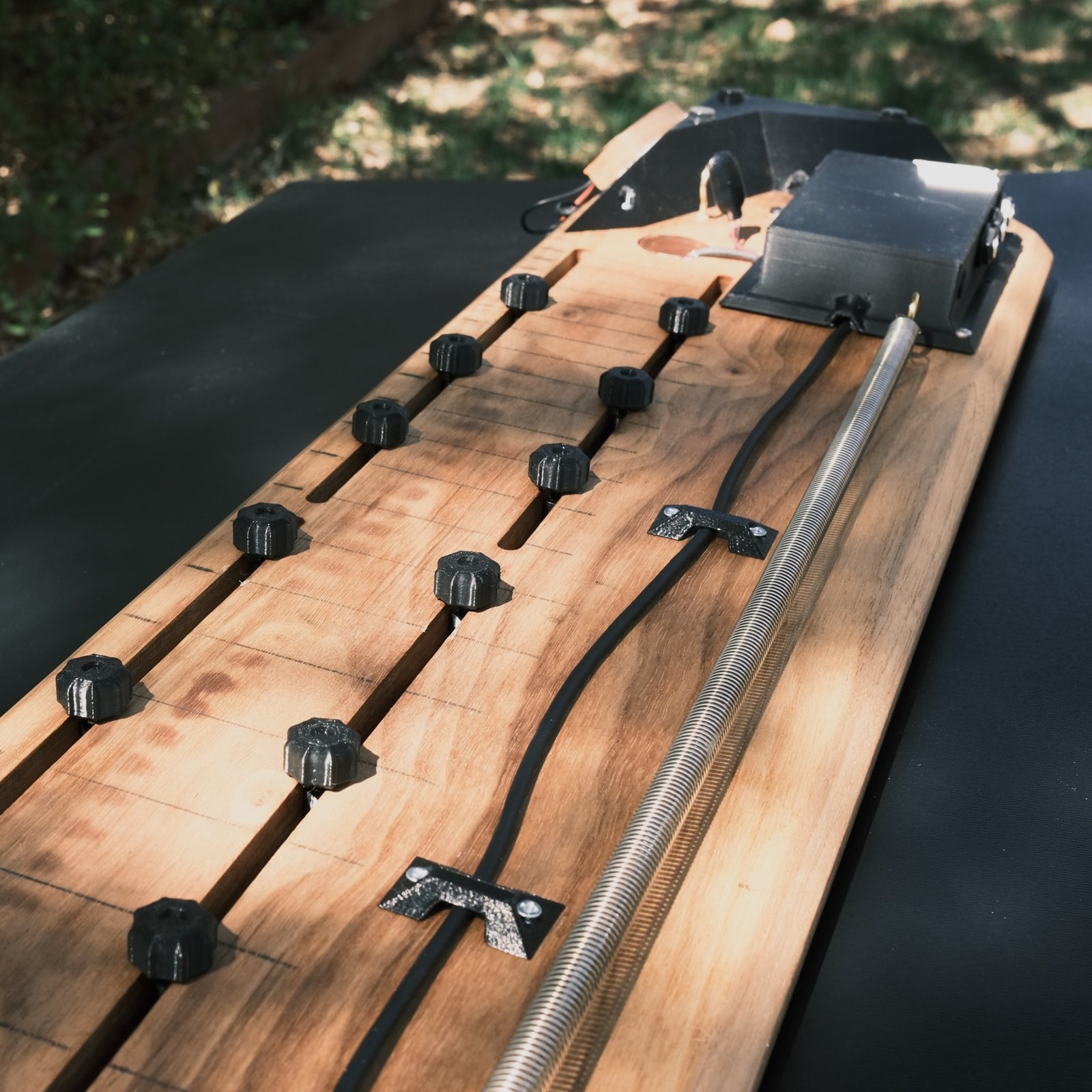
I had this nice walnut board lying around, and also had committed to playing a little gig at a series my friends in Fort Collins run called Noise Floor. So why not make the most out of that hard deadline and try to make an instrument out of the board so I can play it at the show? Given how little I know about electric instruments, this came out surprisingly well, and sounds surprisingly good thanks to the stereo contact mics + pre-amp.
Here are the main features:
Solid walnut body
Moveable frets
2 embedded contact microphones
DIY single coil pickup
Hot-swappable pickup system
Walnut + brass frets w/ 3D printed “legs” that go through the slots
Spring on the bottom for sustain
Custom stereo contact mic PCB
And a demo vid if you want to hear some audio samples.
Here are the main features:
Solid walnut body
Moveable frets
2 embedded contact microphones
DIY single coil pickup
Hot-swappable pickup system
Walnut + brass frets w/ 3D printed “legs” that go through the slots
Spring on the bottom for sustain
Custom stereo contact mic PCB
I used 3D printed router jigs for the slots and other cutouts. For my first time trying this in earnest, and it worked pretty well.
In the making
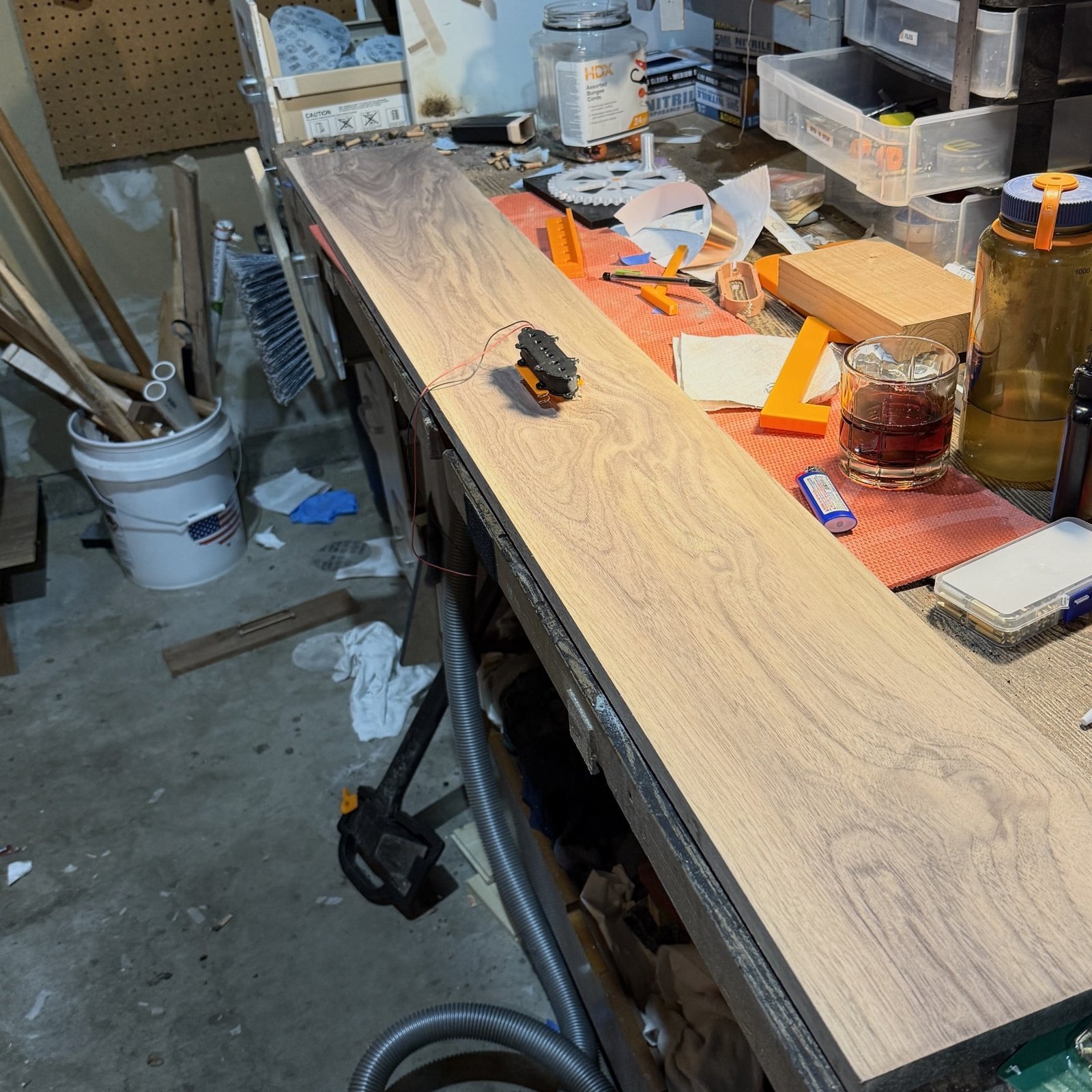
Here is the raw board after surfacing and some sanding.
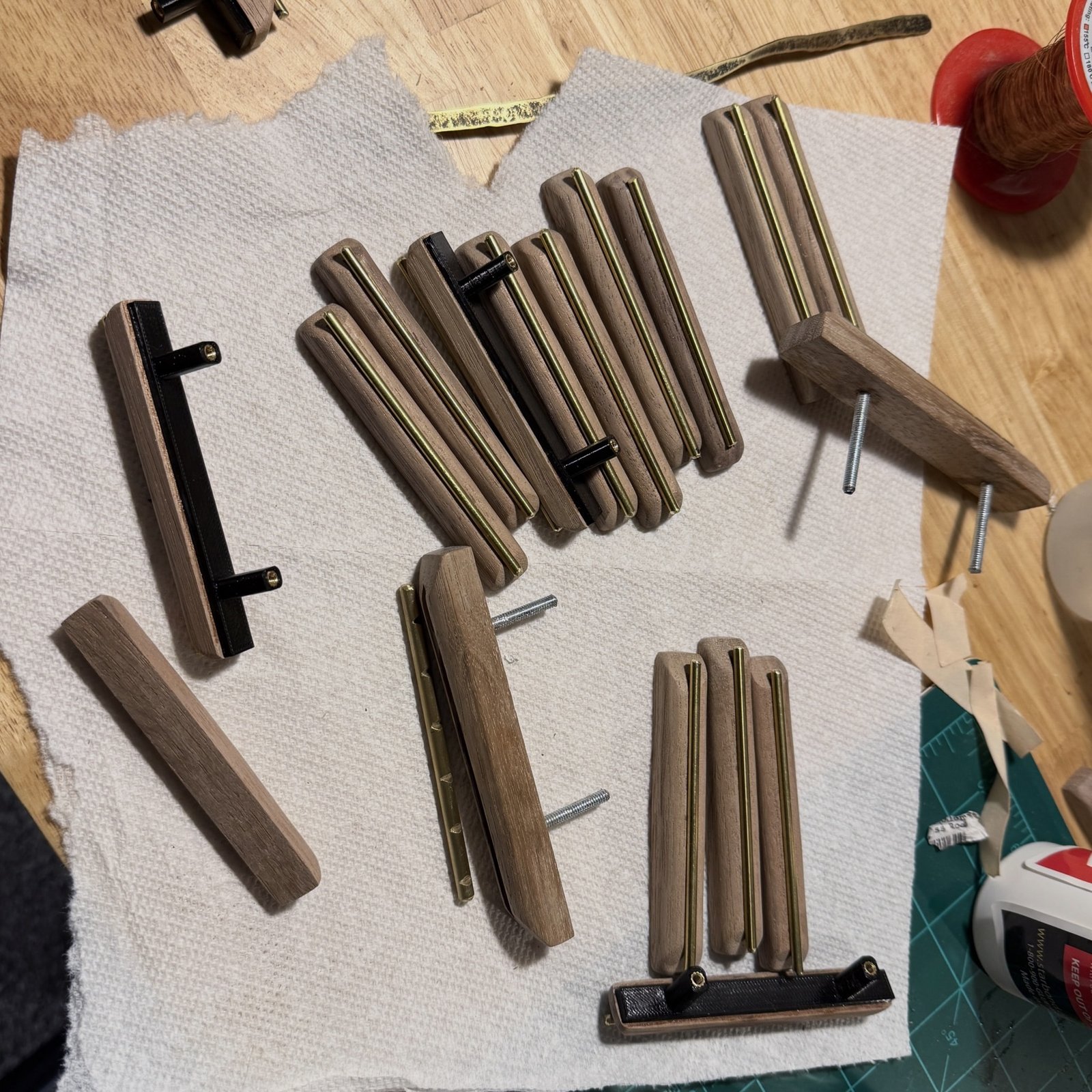
Here you can see the slots on the back, and how the frets are attached. The black knobs are 3D printed caps superglued onto M3 bolts. These feed up into a captured nut within the 3D printed fret attachment.
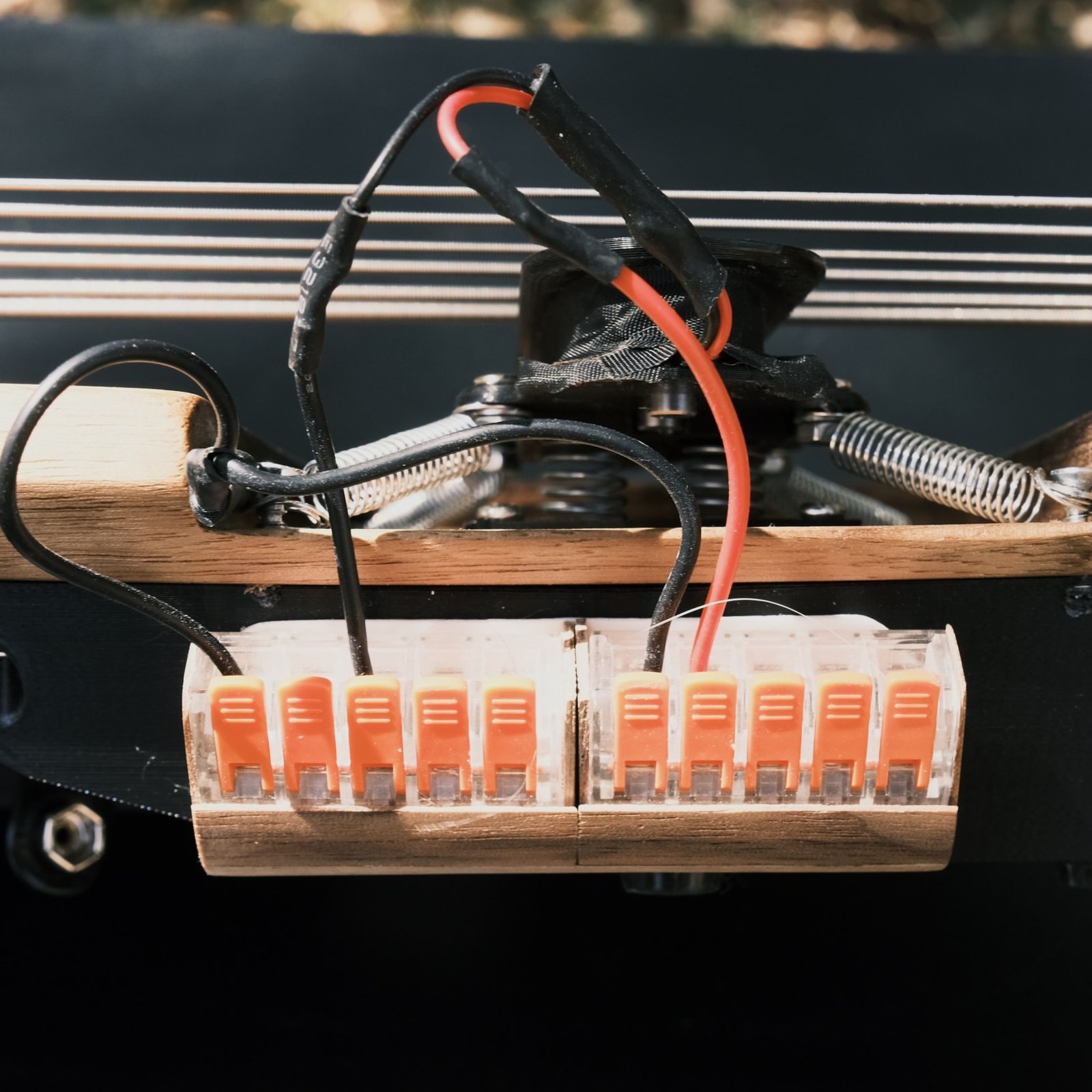
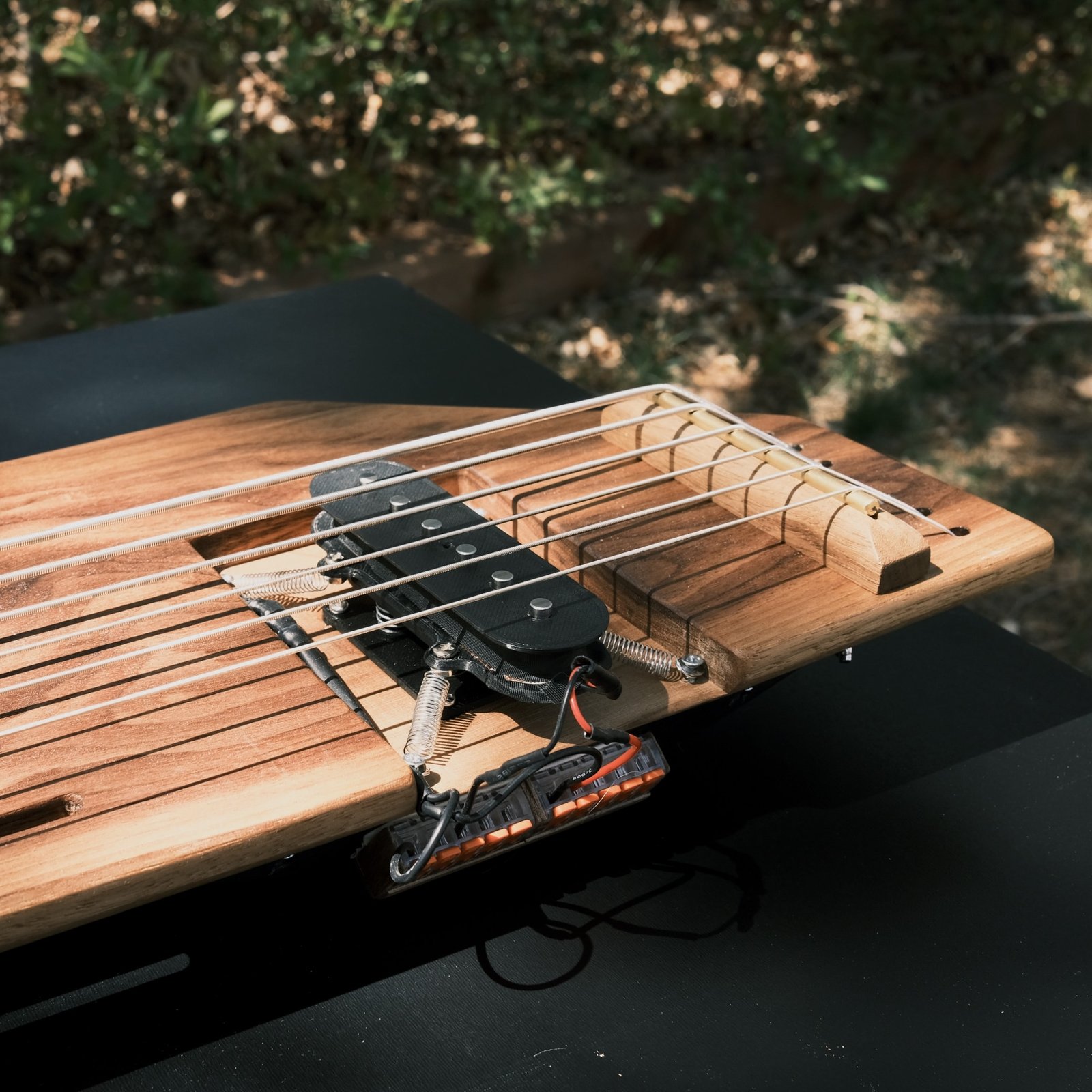
The pickup was created by 3D printing the bobbin, sticking some magnetic pins in it, and winding it with a hand drill jig. I ran out of wire so wasn’t able to spool it completely, hence the not great sound. Thankfully I made it modular, so it’s easy to pop out whenever I get inspired to make a new pickup. Harbor freight lever wire connectors do the Job. I used large ones in case I want to experiment with running multiple pickups in parallel, which I think is a thing you can do?
The pickups are mounted on a spring …. for the purposes of tremolo, was the idea. The problem here is that the contact mics pic up every little spring squeak, so it’s not too practical to move the pickup around while playing unless just using the pickup output.
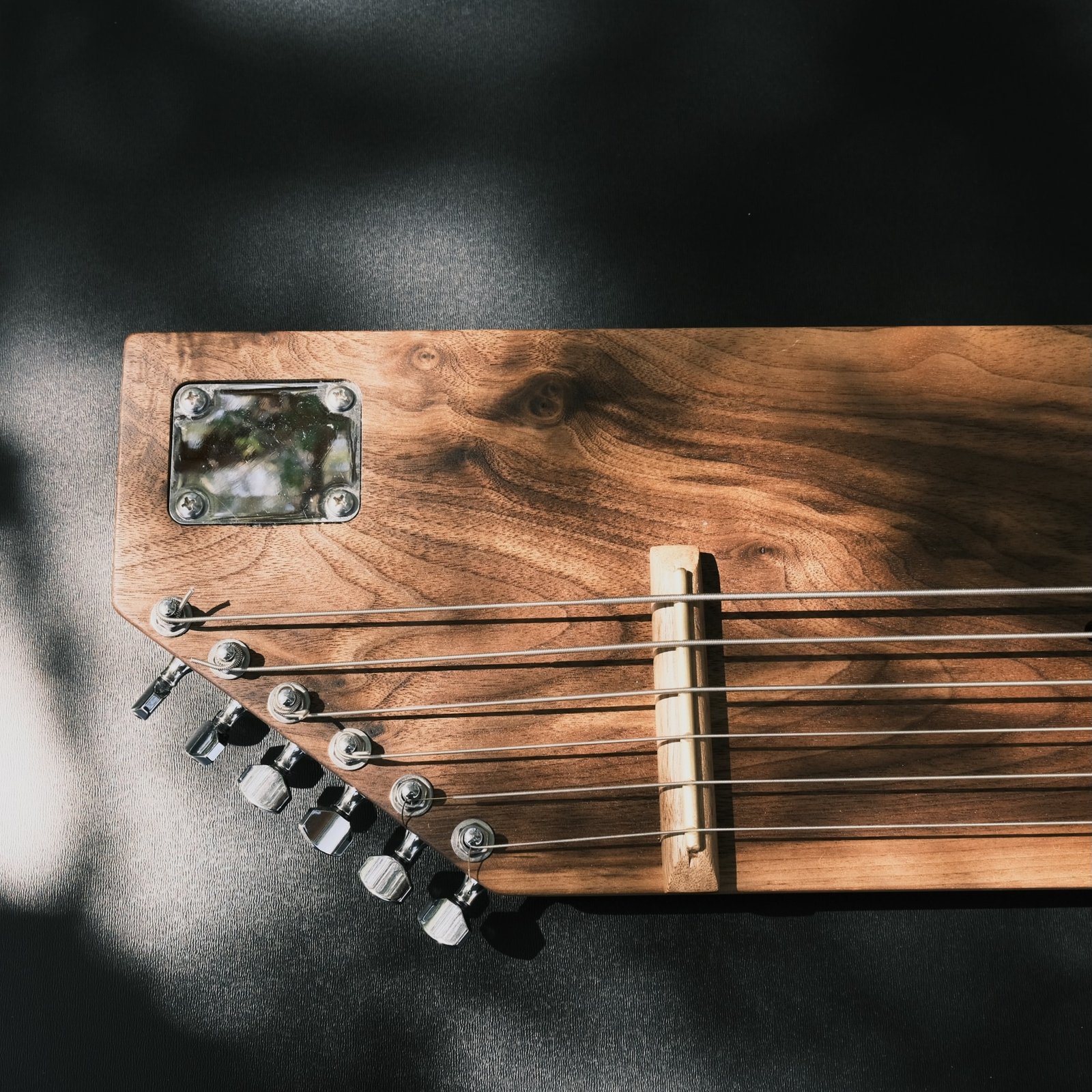
And finally a closeup of one end so you can see the nice walnut grain pattern. I finished it with a hardwax oil – Rubio Monocoat. It has a nice satin finish which I enjoy.
In summary, it’s probably easier to make an electric stringed instrument than you think. If you don’t want to bother with the DIY pickup, just buy one from a used store or online for like 15 bucks. If you don’t want to do that, just grab a piezo disc or 2, solder them to an old aux cable that’s been snipped, and you’re done. So go give it a shot.
I’ve been experimenting with similar designs, but this is the best sounding so far. The idea is to amplify a signal (in this case using a $1 aliexpress amplifier module) and feed it into a an old speaker cone scavenged from who knows what 4 years ago, find a way to run it through a spring, then collect the sound on the other side with 2 contact mics.
TLDR
Attach bolt to middle of speaker cone using hot glue
Attach this bolt to spring(s)
Attach 2 contact mics to a metal plate which is mounted to the other side of the spring
Find a way to stretch the whole thing out
Materials
Speaker cone (I used ~4″ – bigger the better)
Amplifier for speaker (
I used a Estardyn TPA3110 XH-A232 30W+30W 2.0 Channel Digital Stereo Audio Power Amplifier Board DC 8-26V 3A) from Aliexpress (~$1.50)
Bar clamp with long jaws (Harbor Freight)
At least 1 contact mic (You can get hella piezo discs for cheap)
At least 1 large reverb spring
An assortment of smaller springs (harbor freight)
Assorted bolts, etc.
(optional) Contact mic pre-amp
Makes the output sound MUCH better
Soldering tools, pliers, etc.
If I were better at documenting, there would be in-progress photos, but alas.
Steps
Mount Spring To Speaker
Find a way to attach the spring(s) to the bolt on the speaker cone. L brackets that I had lying around worked well for me. You’ll see that I also added 4 smaller springs as support – I was afraid the main spring tension would end up ripping out the middle of the speaker cone, these help make sure it isn’t pulled on to hard. I have no idea if this is necessary or not but it looks kinda cool?
Mount Speaker to Clamp
I just super glued an L bracket to the back and tied a loop of string around it. Seem to work fine for now?
Prepare Contact Mics
Strip your audio cable and solder to your contact mic(s). I used an aux cord for stereo. See my contact mic guide here for more info on this step.
Prepare Contact Mic Plate
Find something metal that you can super glue 1 or 2 piezo elements to, and also has holes for mounting the spring and clamp 2. I used a random plate with holes in it that I had, but get creative.
To prevent dampening on the contact mic side, use springs on the back side of the mounting plate to attach to the other side of the clamp. You can see my setup below. The extra plate is there because I had fabricated it for an abandoned project and it already had a bunch of springs on it.
Setup the Amplifier
Solder an audio input cable to your amplifier and solder the output wires on, which will be connected to your speaker. Connect the output wires to the speaker. Connect power to the amplifier (I made a janky 9V battery clip to barrel converter).
(Optional) Contact Mic Pre Amp
For a fuller sound spectrum, plug your contact mic output into a pre-amp first. Note that this has to be a contact mic specific pre-amp.
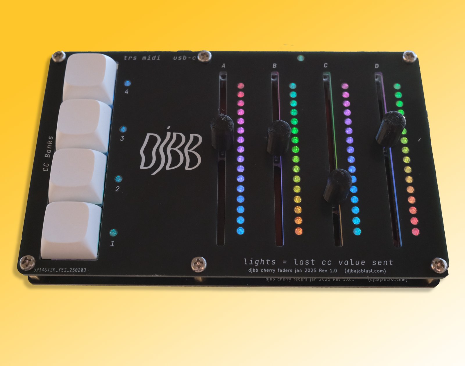
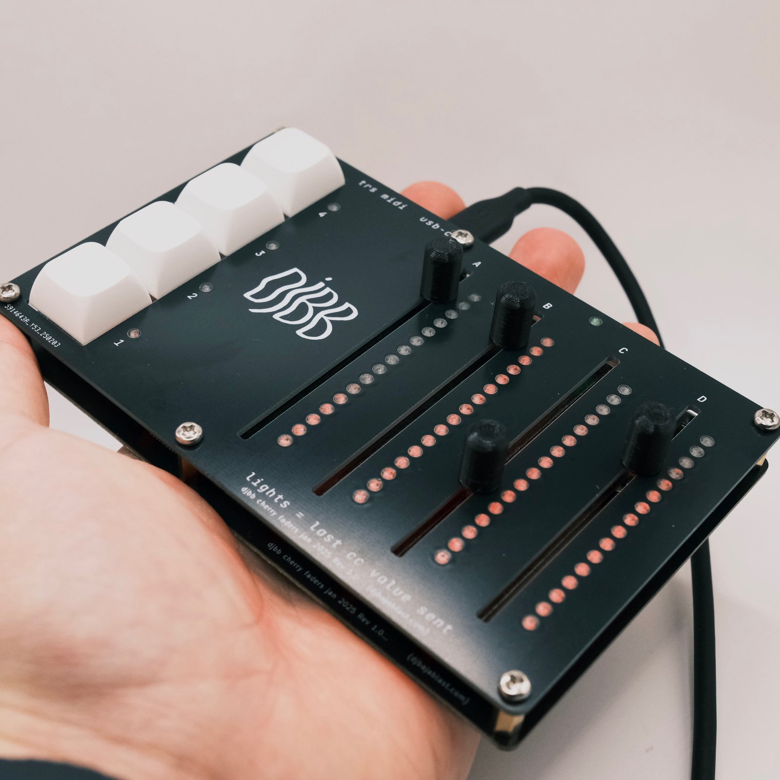
I’m of the opinion that faders are better than twist pots, and wanted something compact that I could use to control a bunch of parameters in an Ableton drum rack. I also wanted to solve the “jumping” problem that you have when using a controller with multiple banks – if you change a bank, you don’t know what the real position of the knob should be, and it’s easy to accidentally jump to a wildly different value than you want just by slightly moving the potentiometer. Here are the features that the LumaFader has, some of which help solve this problem.
Demo
Features
4 x long-throw faders for precise control
4 x mechanical keyswitches for bank management
16x RGB LEDs per fader to show the last fader position for that bank
“Pickup” mode – only send a message when the last value is passed
USB C for easy connection to your computer / phone / whatever
Mini TRS Out to directly connect to a synth
17 banks = 68 total assignable sliders
Usage
I designed this to use with a drum kit in Ableton. For example, you can map the global sliders to overall kit FX (reverb, volume, filter, etc.). Then, map each bank to an individual sample’s parameters. So holding one button will access 4 parameters of the drum sample, holding another button will access 4 parameters of the snare sample, etc.
Move slider(s) to send CC messages
Hold button(s) to access other banks of CCs
Double click a bank button to lock the bank (otherwise the global bank will be used if no buttons held)
CC messages are only sent if the slider moves past the last value sent (as displayed on the LEDs next to each slider)
You can also enable jump mode – send CC messages immediately if the slider is moved
Design
I had already successfully designed a custom PCB based off of the RP2040 – see the Loopster 2.0 – and each time I design a PCB, I try to do something I haven’t done before in order to improve. In this case the new elements were USB C – I’ve only ever used micro USB in the past – and the use of a large number of RGB LEDs (NeoPixels). I’ve used these pixels in the past, but this project uses 69 of them – a good factor of 4 more than the Loopster 2.0 has.
First, I had to add the RP2040 and the associated circuitry. Following the RP2040 hardware design guide I added the appropriate power regulator, memory chip, crystal, and decoupling caps. The only changes I made from the official design:
Swapped the ceramic cap on the power supply with an electrolytic – something that a Redditor suggested. This seems to have eliminated the high pitched buzz you can sometimes hear.
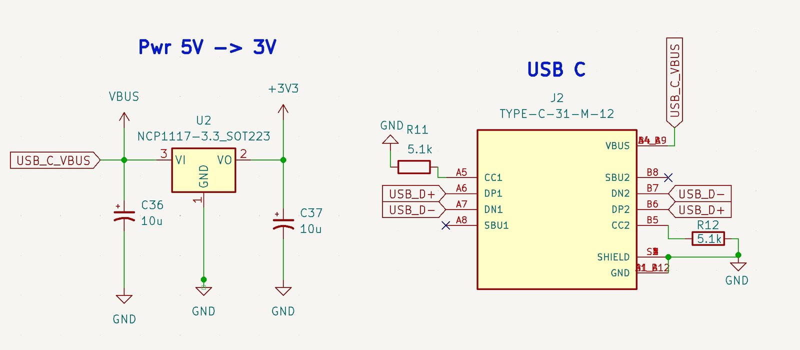
Swapped micro USB for USB-C. This ended up being simpler than I expected – just needed a few extra resistors
power regultor and USB C changes
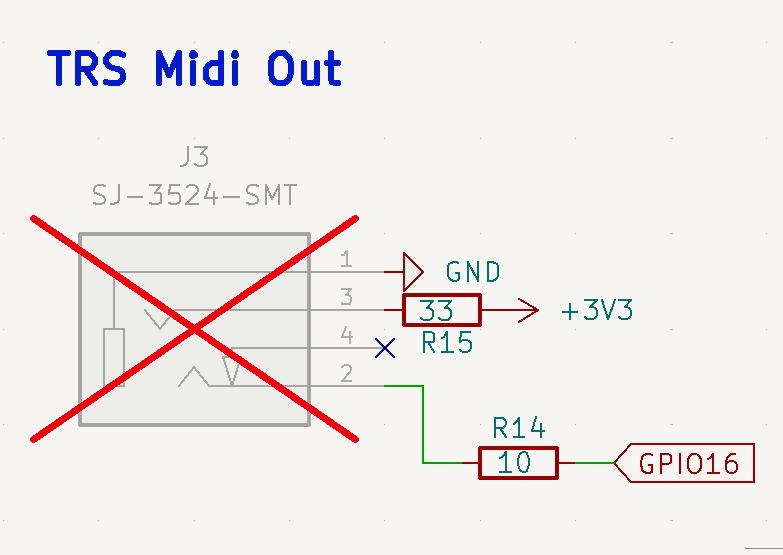
The rest of the circuitry is pretty straightforward – connect the slide pots to the analog pins of the RP2040, connect each button to a digital pin, and then connect the neopixels to one digital pin. These tiny addressable RGB LEDs are great in that they only require ONE digital pin for all of them. Finally, add the TRS MIDI Out circuit, which requires just one more digital pin.
TRS Midi Out Setup
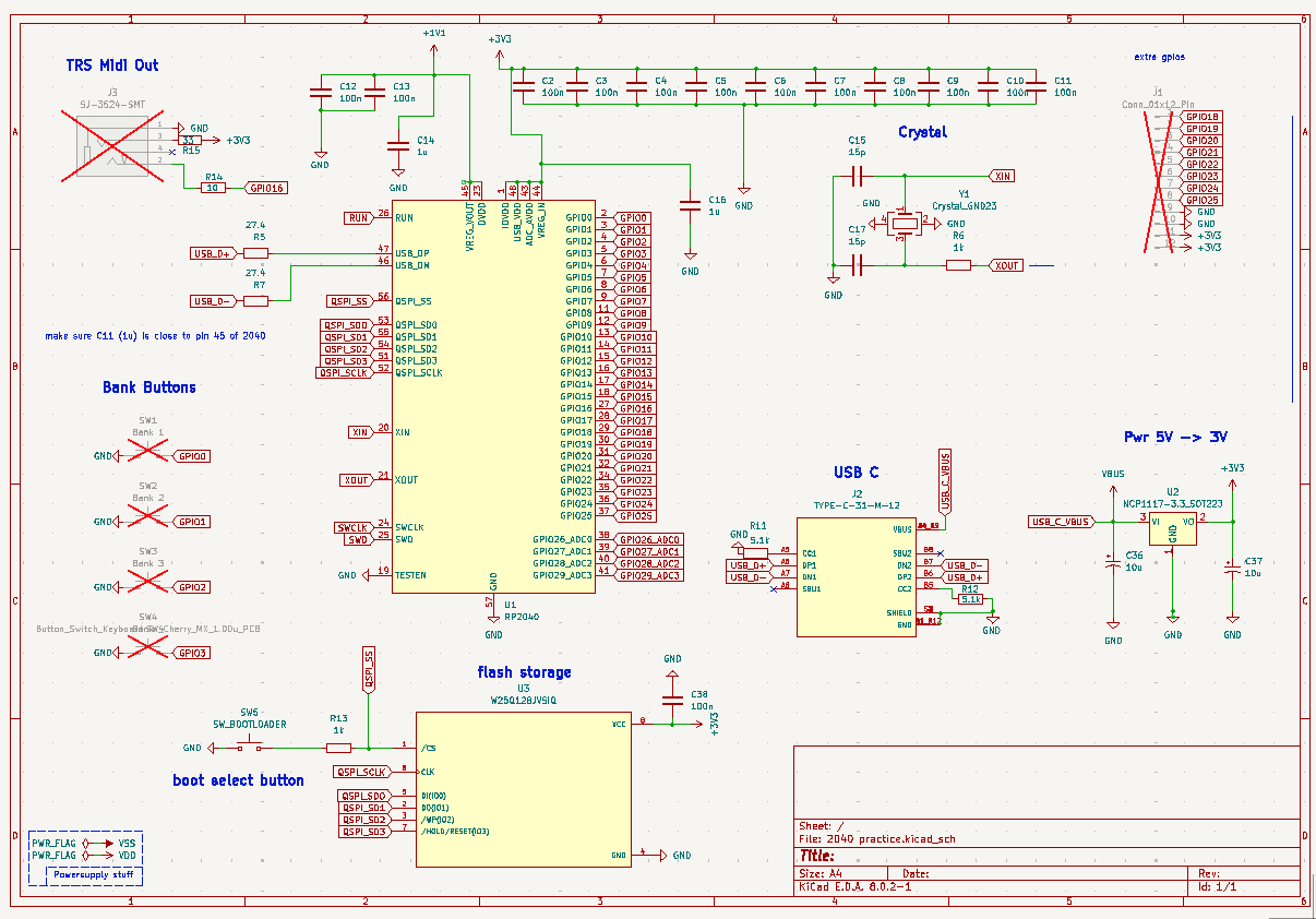
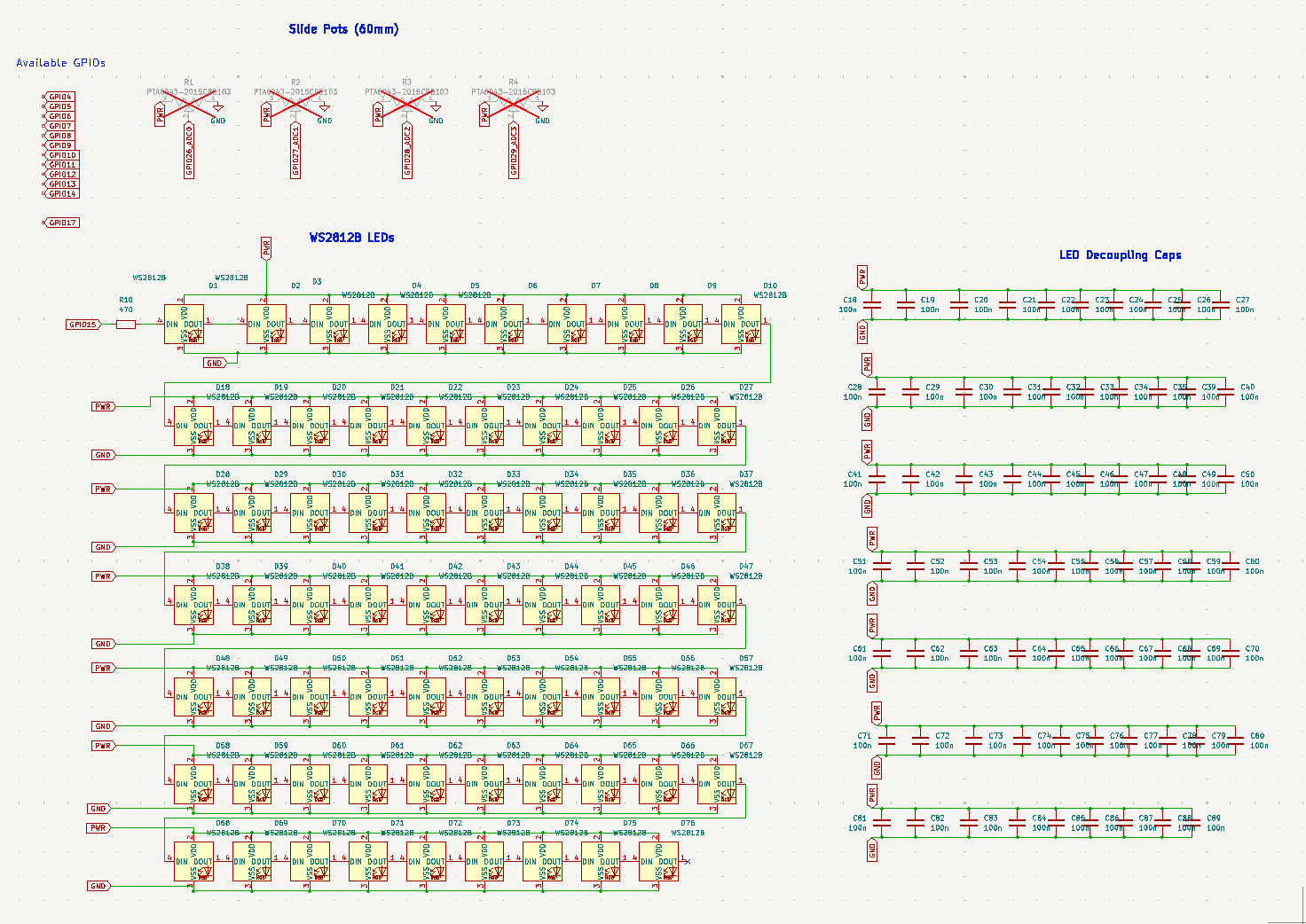
Here is the full schematic
Full Schematic – Main
Full Schematic – LEDs and Pots
Layout
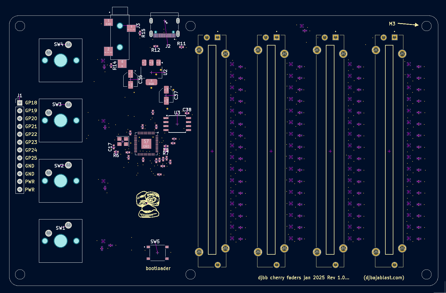
The goal was to make this device compact and portable, so efficient use of space was a priority. I used the middle of the board to house the main circuitry, the left for the buttons, and the right for the 4 large sliders. I decided to break out some additional GPIOs from the RP2040 since I didn’t use them all. I don’t have any plans for these, but perhaps in the future they can be used for something?
PCB Layout
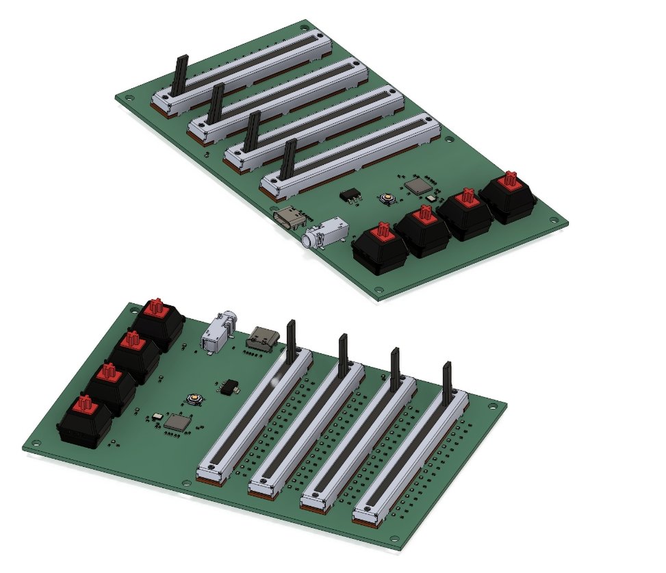
3D Renders
Enclosure
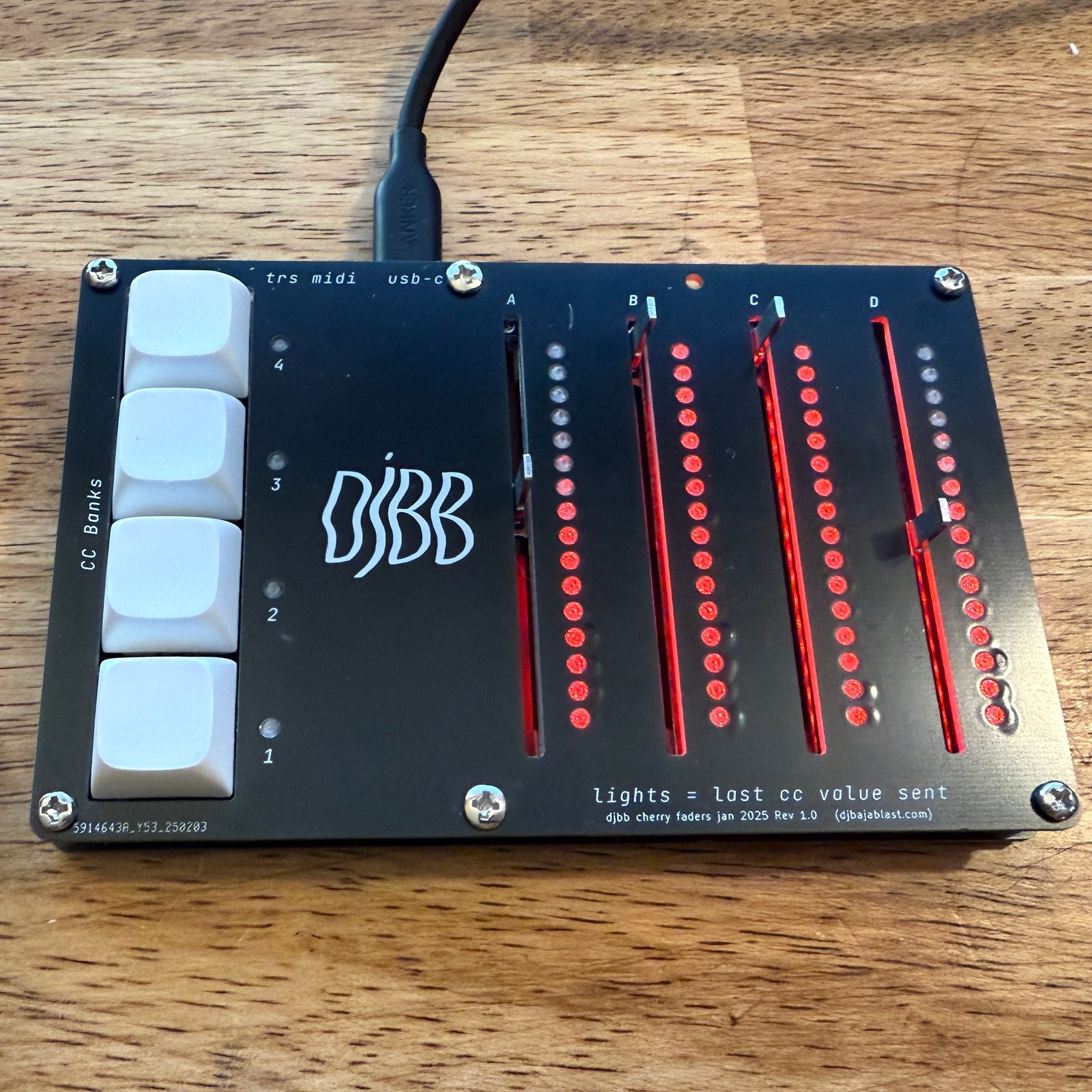
I usually go with a 3D printed enclosure made from PETG, but this time wanted to try the ol’ “PCB Front Panel” trick. I drew up a simple front panel in KiCad and included holes for all of the LEDs, Sliders, and Buttons. I thought they came out great, especially considering how cheap they are to get made. I used some brass standoffs to connect the main board and the front panel.
Assembled device with front panel and diffusers
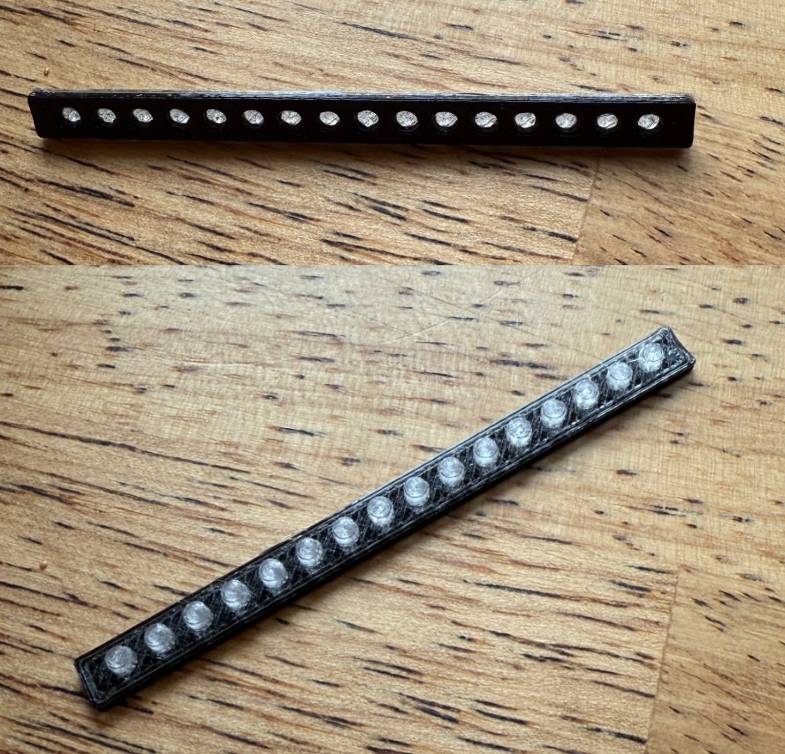
The tiny LEDs shining through the panel holes were a bit harsh, so I designed little diffuser inserts and printed them out of transparent PETG, which did the trick. Note that the bottom layers are printed in black PETG in an effort to prevent too much bleeding between the pixels.
3D printed LED Diffusers
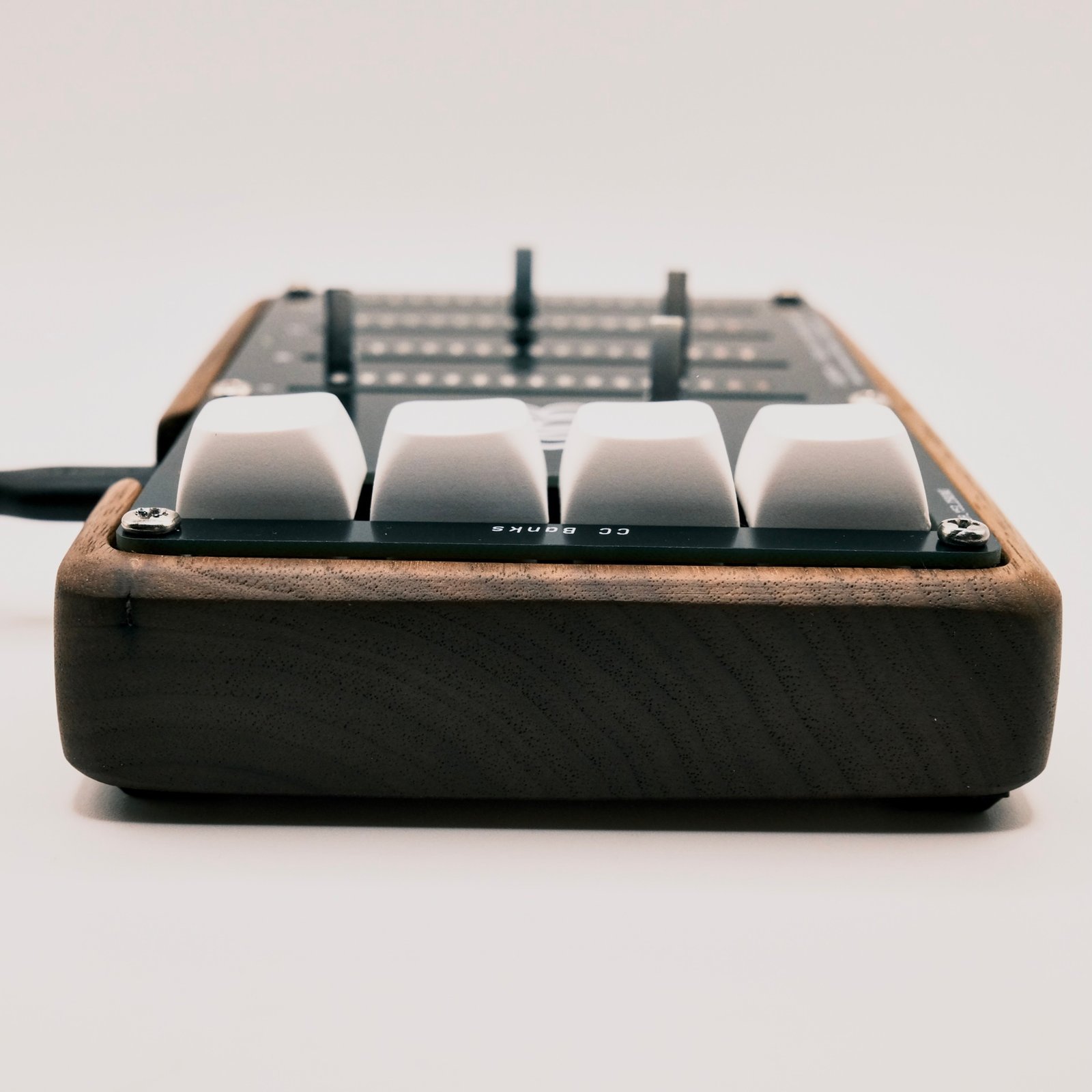
For the hell of it, I also created a nice Walnut case for one of them. I designed a router template in Fusion 360 and hand routed it out of a solid block of walnut. It was then hand sanded to a high grit and finished with a hardwax oil (Rubio Monocoat)
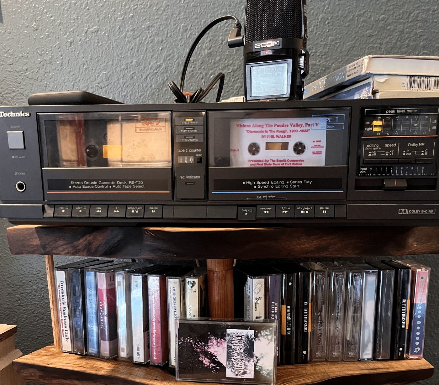
I’ve ripped a lot of tapes over the past few years and finally landed on an efficient method of ripping, tracking, and labeling the tapes. It’s super simple but perhaps it will help. The TLDR version is:
Turn on auto record / auto stop on your field recorder.
Plug an RCA -> aux cable into the field rec device and press record.
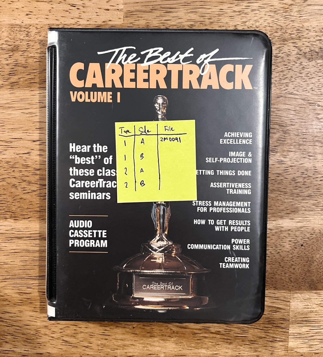
Put a post-it on the cassette shell / record sleeve. Take note of the side, and the filename on the field recorder.
Keep doing this until the SD card is full.
Empty the SD and rename according to your post-its.
Steps
Grab your media, post-it notes, field recorder,and aux to RCA cable
Go into your field recorder settings and turn on auto rec on and off. Experiment with the dB threshold settings. I set the stop threshold to something really close to the minimum, and the auto start recording threshold set to a bit more than that.
At this point you might consider powering your field recorder via a large usb power bank or a brick, if that’s an option. Mine is plugged into a brick and it’s very nice to never think about batteries.
Now you can just press play and let it start recording.
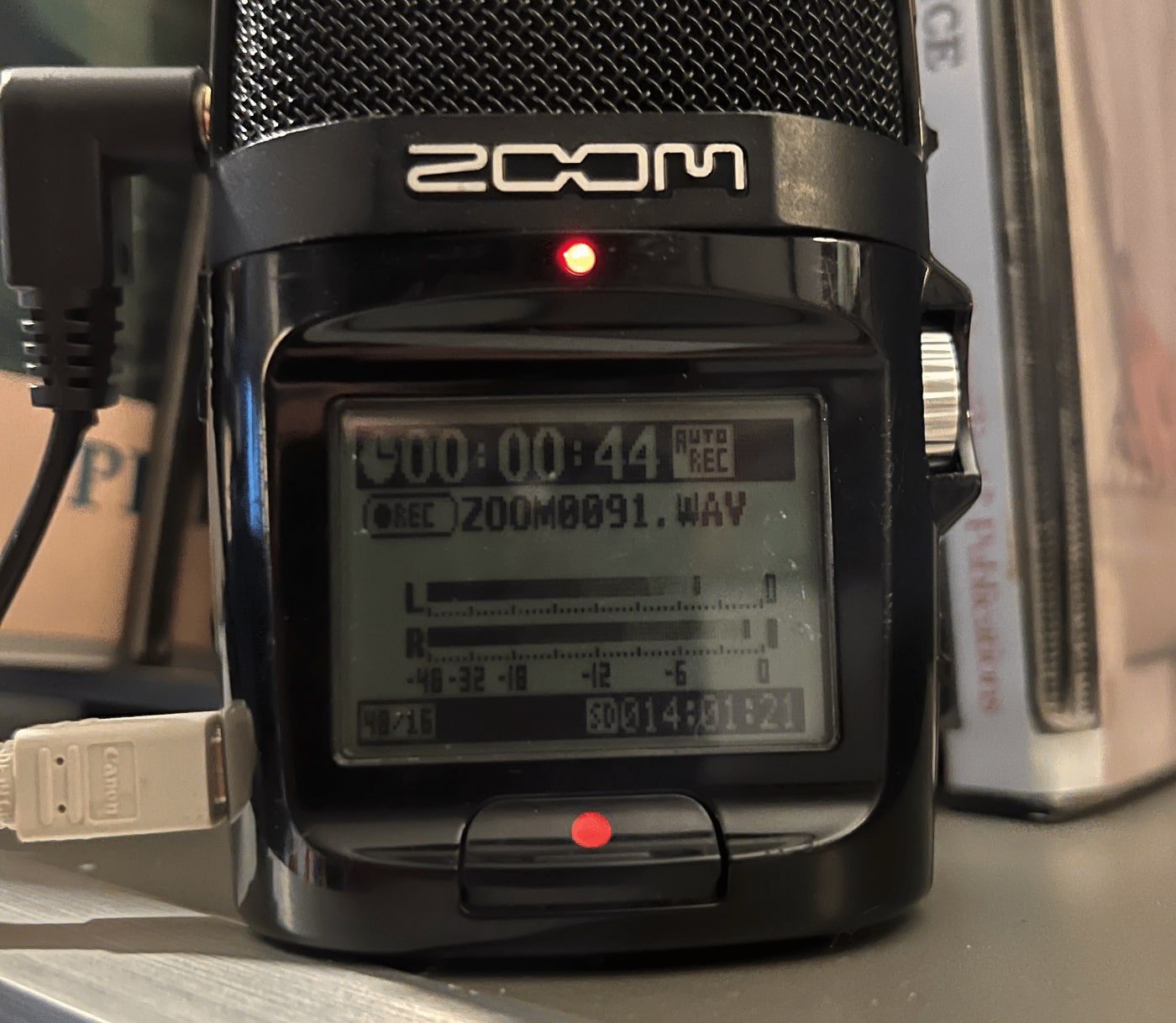
Slap a post-it note on the cover / case and note a reference to the file name of the recording file, and which tape/side it corresponds with.
filename on zoom h2n
post it note with notes about filenames
Repeat until your SD Card is full. With auto record you don’t even need to press record. Just pop out the old and pop in the new and press play.
Transfer the files to your computer.
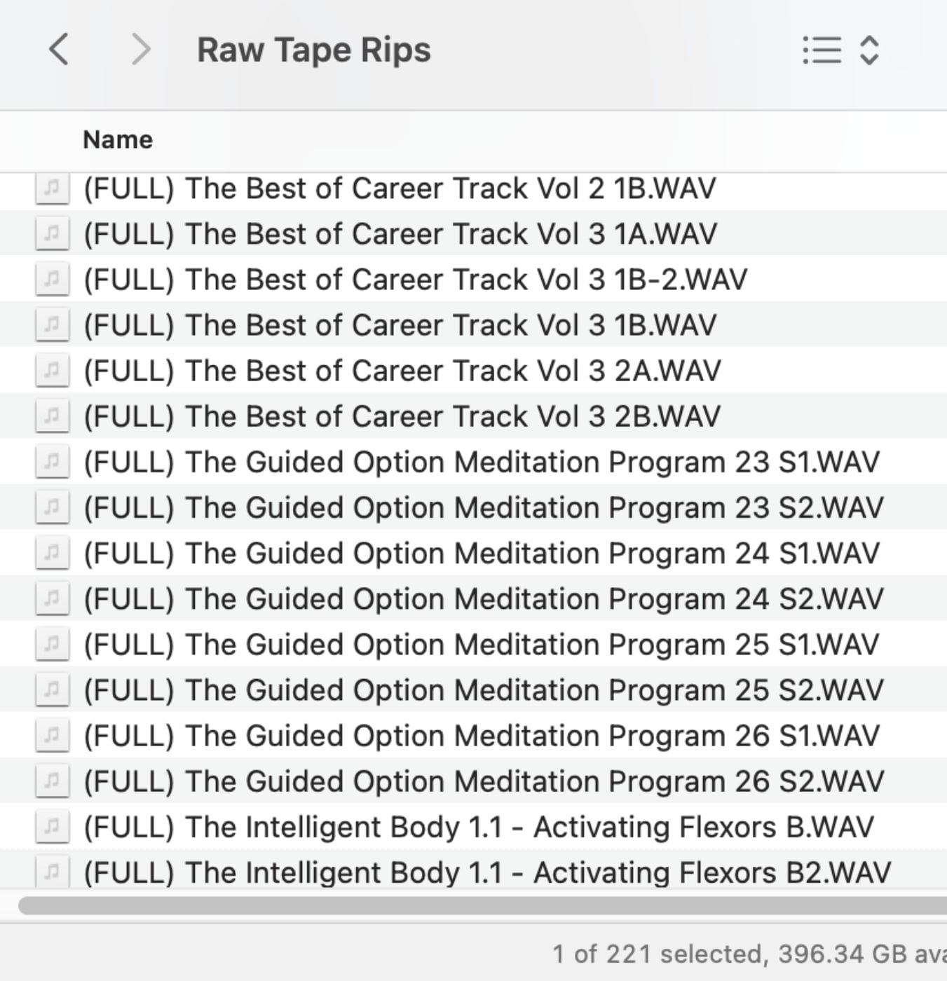
Grab your stack of sticky noted media and reference the filenames with the post its to figure out how to name the file. Here’s what mine usually look like.
final filenames in Finder
Reformat the SD card
Start over and do this forever and ever until you run out of tapes or die
Go to the thrift store and get MORE tapes to feed your addiction
Check into rehab
Relapse. Spend your life’s savings on eBay cassettes.